Furuno GP-1600F Operator'S Manual Download Page 29

2 –5b

Difference between FURUNO chart and NAVIONICS
chart

Table 2-4 FURUNO chart versus NAVIONICS chart

*1 NAVIONICS chart may not center cursor perfectly.

*2 NAVIONICS chart may not center own ship's position perfectly.

A NAVIONICS chart may disappear for some time when the dis-
play is scrolled.

*3 Using newly designed chart cards containing lighthouse data.
Chart cards for North America area are completed, and others are
under production in.

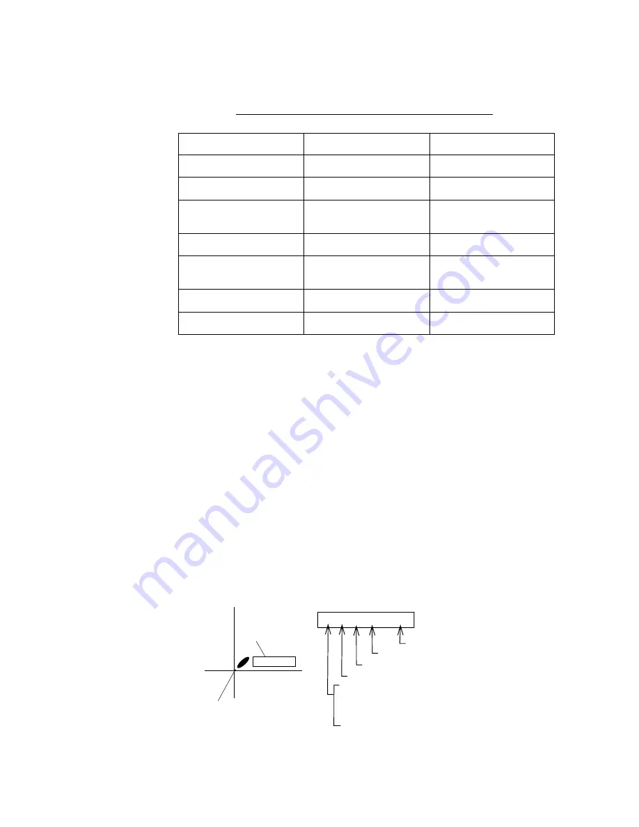
Lighthouse and buoy data display

You can find data of lighthouses and buoys by placing the cursor
on them.

Lighthouse and buoy data are abbreviated on the display as shown
in Figure 2-5.

Figure 2-5 Interpretation of buoy/lighthouse data

Item

FURUNO

NAVIONICS

Dot scrolling capability

YES

YES

Course-up display

YES

NO

Lighthouse data 
presentation

YES *3

YES

Zoom at cursor position

YES

*1

Range at Equator

1, 1.5, 2, 3, 4, 5, 6, 8, 
12...8192 nm

0.125, 0.25, 0.5, 1, 2, 3, 
4, 8...1024 nm

Chart offset data entry

YES

NO

Centering

YES

*2

FL 12S 27M

Place the cursor on
a lighthouse or buoy mark.

Lighthouse or
buoy data

FL(2) G 12S  15M

Number of flashes perperiod (ex.:2)

Period(ex.: 12 seconds)

Visibility in nautical miles(ex.: 15 miles)

FL      : Flashing
F        : Fixed light
F FL   : Fixed and Flashing light
MO     : Morse code light
Oc      : Occulting light 

Light color

Example of data displayed

Summary of Contents for GP-1600F

Page 1: ......

Page 2: ......

Page 3: ...ons please contact a FURUNO agent or dealer SAFETY INSTRUCTIONS DANGER This notice indicates a potentially hazardous situation which if not avoided will result in death or serious injury This notice indicates a potentially hazardous situation which if not avoided could result in death or serious injury This notice indicates a potentially hazardous situation which if not avoided could result in min...

Page 4: ......

Page 5: ...5 2 23 Setting Event Position as Destination 2 25 2 24 Changing Event Mark Shape 2 25 2 25 The MOB Function 2 25 2 26 Stopping Plotting of Track 2 26 2 27 Changing Track Plotting Interval 2 27 2 28 Erasing All Track Marks 2 27 3 VIDEO SOUNDER OPERATION 3 1 Principle of Operation 3 1 3 2 Video Sounder Displays 3 2 3 3 Automatic Video Sounder Operation 3 6 3 4 Manual Video Sounder Operation 3 7 3 5 ...

Page 6: ...eceiver Status Indication 6 5 6 6 Troubleshooting Table 6 6 6 7 Memory Card Operations for technicians 6 8 6 8 Demonstration Display 6 9 6 9 Installation of New Program for technicians 6 10 6 10 Clearing the Memory 6 10 APPENDIX Specifications A 1 World Time Standards A 3 Geodetic Chart List A 4 Loran C Chains A 5 Decca Chains A 6 INDEX ...

Page 7: ... equipment This dedication to excellence is furthered by our extensive global network of agents and dealers This equipment is designed and constructed to meet the rigorous demands of the marine environment However no machine can perform its intended function unless operated and maintained prop erly Please carefully read and follow the recommended procedures for operation and maintenance We would a...

Page 8: ...nsive navigation data displays Bright 6 inch LCD with temperature compensated tone and bril liance control Automatic coastline chart loading Position display in latitude and longitude Loran C LOPs or Decca LOPs Outputs steering information to FURUNO autopilots FAP 50 55 300 330 Improved position accuracy with connection of DGPS beacon receiver option FURUNO and NAVIONICS chart cards Memory capacit...

Page 9: ......

Page 10: ...play Enters marks event marks and MOB mark Sets cancels destination Zooms out plotter display Turns cursor on off Erases marks waypoints silences aural alarm Turns power on off Displays main menu escapes current operation Selects video sounder display Turns on automatic adjustment of video sounder picture Enters waypoints Zooms in plotter display Centers cursor and own ship s position Enables adju...

Page 11: ......

Page 12: ...y to adjust display brilliance 1 7 Plotter Displays The PLTR key selects a plotter display among normal plotter plotter video sounder data graphic and highway Normal plotter display North up presentation WP001 120 223 8nm CSE 180 SPD 16 8kt 3D DEP 113 6 ft TMP 16 0 C 12 0V POS 34 26 345 N 135 41 232 E L L Own ship mark Course bar Track Chart icon Range and bearing to destination waypoint Ship s co...

Page 13: ...course and speed Depth and water temperature Position Receive mode or alarm message Ship s mains voltage 200k 0 50 100 150 200 Plotter display Sounder display Figure 1 7 Plotter video sounder display Digital data display This display provides position course speed depth water tem perature optional sensor required range bearing and XTE Cross Track Error the amount in nautical miles your boat is off...

Page 14: ...E S W BRG 248 CSE 323 1nm 1nm TRIP RNG ETA TTG 789nm 1123nm 23 20 14H 20M Own ship s position XTE amount in nautical miles boat is off course and amount to steer to return to intended course Time to Go to destination Estimated Time of Arrival at destination Ship s course Trip distance Range to destination waypoint Bearing to destination waypoint Figure 1 9 Graphic data display with autopilot conne...

Page 15: ...operating status These icons are as follows Figure 1 11 Plotter display icons L L H Chart icons See page 2 4 Chart position offset applied L L position offset applied Track recording plotting turned off Alarm setting violated Low voltage of internal battery DE MO Demonstaration mode ...

Page 16: ...e graph Tone bar Depth C 30 20 10 0 Water temperature display Figure 1 12 Normal video sounder display Note The water temperature display requires a triducer or water temperature sensor option Marker zoom display This display provides an expanded view of the area within the Vari able Range Marker VRM and the zoom marker It is useful for judging the size of midwater fish 200k 162 0 50 100 150 200 9...

Page 17: ...80 Figure 1 14 Bottom zoom display plus normal display Bottom lock display The bottom lock display provides an expanded wide or nar row view distance depends on unit of measurement of the area above the seabed This display is useful for discriminating fish near the seabed 200k 162 0 50 100 150 200 68 3 CSE 180 0 SPD 16 8kt DEP 113 6 ft TMP 16 0 C 2D 12 0V POS 34 26 245 N 135 41 232 E Bottom lock d...

Page 18: ... their intensities on the right 1 3 of the screen It is useful for estimating the kind of fish school and sea bed composition 200k 160 0 50 100 150 200 68 3 CSE 180 0 SPD 16 8kt DEP 113 6 ft TMP 16 0 C 2D 12 0V POS 34 26 245 N 135 41 232 E Normal display A scope display Figure 1 16 A scope display right side ...

Page 19: ... Sel ESC Esc Figure 1 17 MAIN menu 2 Press appropriate numeric key or press key and NU CU ENT key to select menu The highlighted cursor shifts with key operation 3 Press or key to select menu item 4 Press t or s key to select option 5 Press the ESC key to close menu Note In some cases it may be necessary to press the NU CU ENT key after selecting option Entering numeric data The entry of leading z...

Page 20: ...8 W MARK _ _ CMNT PORT ts Cursor Column ENT Enter N S E W ESC Escape 34 45 567 N 135 23 321 W 34 45 231 N 135 33 456 W 34 42 316 N 135 21 678 W Plotter menu Video sounder menu Destination waypoint menu EVENT LIST No LAT LONG 001 34 45 678 N 135 35 321 W 002 34 45 231 N 135 35 456 W Cursor ENT Enter MENU Sel Mode ROUTE ROUTE LIST REVERSE No PTS TOTAL TTG 01 5 1234 56nm 10 40 02 20 2345 67nm 22 36 S...

Page 21: ...ACK USED 0 2000 PT Cursor s Go ESC Esc ROUTE ROUTE LIST No PTS TOTAL TTG 01 5 1234 56nm 10 40 02 20 2345 67nm 22 36 Cursor ENT Sel ESC Esc CLR Deleat Route In use ALARM SETUP 1 2 ARRIVAL ARRIVAL ANCHOR OFF Range 00 500nm XTE ON OFF Range 00 250nm SPEED WITHIN OVER OFF Speed 11 0 15 0kt TEMP WITHIN OVER OFF Temp 11 0 15 0 C TRIP ON OFF Range 005 00nm ts Cursor ESC Esc ALARM SETUP 2 2 FISH ON OFF Ra...

Page 22: ...TOP ON OFF ts Cursor ESC Esc DGPS SETUP DGPS ON OFF RTCM VER 1 0 2 0 BYTE FORM 8 6 8 8 FIRST BIT MSB LSB PARITY BIT EVEN ODD NONE STOP BIT 1 2 BIT RATES 7 8 BAUD RATES 300 600 1200 2400 4800 9600 RS TYPE 422 232C ts Cursor ENT Sel ESC Esc CHART POSN CALIB POSN CALIB OFF ts ON CALIB 00 000 N 00 000 E GEODETIC WGS 84 ENT Ent ESC Esc UNIT SETUP DISTANCE nm km sm DEPTH m ft fa TEMP C F ts Cursor ESC E...

Page 23: ...u disappears after 10 seconds Plotter display description Normal plotter display This display traces the ship s track on the screen Coastline charts provided on chart cards option dis play the coastline of your area Navigation data is digitally dis played Plotter Sounder display This display provides the plotter dis play on the left 3 4 of the screen and video sounder picture on the right 1 4 It i...

Page 24: ...e error and the relation between own ship and waypoint Own ship marker North up Course up North marker Figure 2 2 North up and course up presentation modes Selecting presentation mode Press the NU CU ENT key more than one second Each time that keying sequence is repeated the presentation mode changes to either course up or north up The north up mark ap pears at the bottom of the display and the ow...

Page 25: ...rsor large size WP001 120 223 8nm BRG 331 1 RNG 12 3nm 2D DEP 113 6 ft TMP 16 0 C 12 0V CUR 34 26 345 N 135 41 232 E Figure 2 3 Display showing location of cursor data Note The size of the cursor can be set for large or small on the DISPLAY SETUP menu 2 4 Chart Cards The chart cards contain nautical charts When you insert a suitable chart card in the drive and your boat is near land a chart appear...

Page 26: ... i u S Indices and chart enlargement FURUNO charts only When the ZOOM OUT key is pressed you will see several frames These frames are called indices and they show you what parts of the chart can be enlarged in the current chart scale The areas cir cumscribed with smaller frames can be enlarged but the area en closed by the largest frame cannot Figure 2 4 Sample chart Japan and South Korea Notice o...

Page 27: ...elow shows chart symbols and their meanings for FURUNO digital charts Table 2 2 FURUNO digital chart symbols Symbol Description Symbol Description Summit Wreck Lighthouse Lighted Buoy Buoy Radio Station Position of Sounding Obstruction Fishing Reef Platform Anchorage ...

Page 28: ......

Page 29: ... on them Lighthouse and buoy data are abbreviated on the display as shown in Figure 2 5 Figure 2 5 Interpretation of buoy lighthouse data Item FURUNO NAVIONICS Dot scrolling capability YES YES Course up display YES NO Lighthouse data presentation YES 3 YES Zoom at cursor position YES 1 Range at Equator 1 1 5 2 3 4 5 6 8 12 8192 nm 0 125 0 25 0 5 1 2 3 4 8 1024 nm Chart offset data entry YES NO Cen...

Page 30: ...RS key to turn on the cursor if it is not currently displayed 2 Operate the Arrow keys to set the cursor on the location you want to center 3 Press the CNTR key Note NAVIONICS chart may not center cursor position perfectly Scrolling the display 1 Press the CURS key to turn off the cursor if it is currently displayed 2 Operate the Arrow keys to scroll the display in direction de sired The display i...

Page 31: ... can enter a waypoint by the cursor through the waypoint list manual input of latitude and longi tude by own ship s position by event position Entering waypoints by the cursor 1 Press the WPT key The menu for selection of waypoint entry method appears SELECT WPT MODE ENT Sel ESC Cancel Own Position Cursor WPT List Event to WPT Figure 2 7 Display for selection of waypoint entry method 2 Press the o...

Page 32: ...s the NU CU ENT key to enter waypoint and escape 5 To enter a special mark at the waypoint position press the key to place the cursor on the MARK line The following dis play appears SP SP Cursor ENT Enter ESC Escape Figure 2 9 Window for selection of waypoint mark 6 Operate the Arrow keys to select a mark and then press the NU CU ENT key The display for entry of waypoint com ment appears ABCDE FGH...

Page 33: ... at own ship s position 1 Press the WPT key The menu for selection of waypoint entry method appears 2 Press the key to select Own Position 3 Press the NU CU ENT key 4 Change waypoint number if desired 5 Press the key to select mark shape and enter a comment as explained in Entering waypoints by the cursor or press the NU CU ENT key to enter waypoint and escape Entering waypoints through the waypoi...

Page 34: ... select a mark shape and enter a comment as explained in Entering waypoints by the cursor or press the NU CU ENT key to enter waypoint and escape Entering waypoints by event position 1 Press the WPT key 2 Press the key to select Event to WPT 3 Press the NU CU ENT key The event list appears 4 Press the or key to select event position to enter as a waypoint 5 Press the NU CU ENT key 6 Change waypoin...

Page 35: ... CU ENT key The confirmation window ap pears OVER WRITE ENT YES ESC NO Figure 2 13 Window for over writing waypoint data 6 Press the NU CU ENT key The Editor display appears 7 Press the NU CU ENT key To change position operate the t or s key to select digit in position to change and press appropriate numeric key 8 Press the key to go to the MARK line Select mark and press the NU CU ENT key 9 The c...

Page 36: ...ress the NU CU ENT key The waypoint list appears 4 Press the or key to select waypoint number 5 Press the CLR key The confirmation window appears 6 Press the NU CU ENT key 2 10 Setting Canceling Destination Waypoint The GP 1600F offers three methods by which you can set destina tion by waypoint in waypoint list by event list discussed later in this chapter by route list discussed later in this cha...

Page 37: ...lease MENU Sel Mode In use 34 45 567 N 135 23 321 W 34 45 231 N 135 33 456 W 34 42 316 N 135 21 678 W Figure 2 15 Waypoint list 4 Operate the or keys to select a waypoint number 5 Press the NU CU ENT key A dashed line runs between waypoint selected and own ship s position The range and bearing to the destination appear at the bottom of the display WP001 120 0 223 8nm CSE 180 0 SPD 16 8kt 2D DEP 11...

Page 38: ...o another involves several course changes requiring a series of route points waypoints which you navigate to one after another The sequence of waypoints leading to the ultimate destination is called a route The GP 1600F can automatically advance to the next waypoint on a route so you do not have to change the destination waypoint repeatedly Destination 04 03 02 01 00 Own Ship Figure 2 17 Sample ro...

Page 39: ... the cursor on location for destination waypoint 5 Press the NU CU ENT key To clear entry press the CLR key 6 Repeat steps 4 and 5 to complete the route Note Any route waypoints you enter here will also be entered on the waypoint list 7 Press the NU CU ENT key 8 Select route number If you do not want to store the route permanently press the MENU ESC key to escape 9 Press the NU CU ENT key A dashed...

Page 40: ...e list One advantage of this method is that you can use waypoints you have already entered 1 Press the MENU ESC key 2 Press the 4 key to display the ROUTE ROUTE LIST ROUTE ROUTE LIST No PTS TOTAL TTG 01 5 1234 56nm 10 40 02 20 2345 67nm 22 36 Cursor ENT Sel ESC Esc CLR Delete Route In use Figure 2 20 ROUTE ROUTE LIST 3 Press the or key to select route number 4 Press the NU CU ENT key The route ent...

Page 41: ...7 to complete the route 9 When the route is completed press the MENU ESC key three times to escape 2 12 Setting Trial Speed The TTG between legs on the route is calculated based on the trial speed which is entered in the route route list The default speed is 10 knots To enter a different speed do the following 1 Press the MENU ESC key 2 Press the 4 key to select ROUTE ROUTE LIST The route route li...

Page 42: ...ich you want to follow 6 If you want to navigate the waypoints of the route in the order reverse of which they were entered press the key Direc tion selected appears at the top of the display 7 Press the NU CU ENT key An asterisk appears to the left of route selected Route appearance on the display A dashed line connects all waypoints including own ship s po sition Range and the bearing to the fir...

Page 43: ... to skip 7 Press the key to skip that point temporarily The route waypoint number becomes dim 8 Press the NU CU ENT key 9 Press the MENU ESC key twice to escape Restoring route waypoints When you want to restore a route waypoint press the key in step 7 of the above procedure Waypoint number appears in nor mal brilliance 2 15 Cancelling Route Navigation 1 Press the GOTO key 2 Press the CLR key 3 Pr...

Page 44: ...OB key enters marks When the key is pressed a mark an event mark or MOB mark appears on the display depend ing on menu setting To enable entry of marks on the display do the following 1 Press the MENU ESC key 2 Press the 0 key to select SYSTEM MENU 3 Press the 2 key to select PLTR SETUP PLTR SETUP NAVAID OWN LC DC ALL SCALE SCALE RANGE SMOOTHING 00 00 15 SPD AVERAG 00 min BEARING TRUE MAG MAG CALI...

Page 45: ...RK SETUP menu appears at the cursor location or current ship s position 2 18 Changing Mark Attributes Changing mark size You may change the size of marks to small or large 1 Press the MENU ESC key The main menu appears 2 Press the 2 key to select TRACK MARK SETUP TRACK MARK SETUP EVENT SHAPE MARK SHAPE LINE TYPE MARK BRT DIM MARK SIZE L S PLOT ON OFF PLOT INTVL TIME DIST AUTO 00 10 00 10nm Cursor ...

Page 46: ...rn on the cursor 2 Operate the Arrow keys to place the cursor on the mark to erase 3 Press the CLR key 2 20 Connecting Marks Marks can be connected with solid or dashed lines This feature is useful for denoting important areas 1 Press the MENU ESC key 2 Press the 2 key to select TRACK MARK SETUP 3 Operate the Arrow keys to select LINE TYPE to other than single dot 4 Press the MENU ESC key 5 Press ...

Page 47: ...01 to 100 001 being the latest When the event position memory be comes full several beeps are released when the EVENT MOB key is pressed To enter event marks erase unnecessary event marks Enabling entry of event marks To enable entry of event marks do the following 1 Press the MENU ESC key 2 Press the 0 key to select SYSTEM MENU 3 Press the 2 key to select PLTR SETUP 4 Press the or key to select E...

Page 48: ...keys to select an event number 6 Press the NU CU ENT key 2 24 Changing Event Mark Shape 1 Press the MENU ESC key 2 Press the 2 key to select TRACK MARK SETUP 3 Press the Arrow keys to select EVENT MARK and shape desired 5 Press the MENU ESC key to close the menu 2 25 The MOB Function The MOB Man OverBoard function can be enabled on the DIS PLAYSETUPmenu When enabled the EVENT MOB key func tions to...

Page 49: ...s the CLR key The confirmation window appears 3 Press the NU CU ENT key Note To erase the MOB mark clear the memory For further de tails see page 6 10 2 26 Stopping Plotting of Track When your boat is at anchor or returning to port you probably won t need to record its track You can stop recording the track to con serve the track memory as follows 1 Press the MENU ESC key 2 Press the 2 key to sele...

Page 50: ...rack only when the boat is moving thus no track is saved to the memory when your boat is dead in water AUTO changes with chart scale automatically 4 For time or distance enter interval 5 Press the MENU ESC key to close the menu 2 28 Erasing All Track Marks You can erase all track and marks except MOB mark as follows 1 Press the MENU ESC key 2 Press the 3 key to select ERASE TRACK MARK ERASE TRACK ...

Page 51: ...n be determined The entire process begins in the display unit Transmitter power is sent to the transducer as a short pulse of electrical energy The electrical signal produced by the transmitter is converted into an ultrasonic signal by the transducer and transmitted into the water Any reflected signals from intervening objects such as a fish school are received by the transducer and converted back...

Page 52: ...on and general sounding It is especially useful for discerning seabed hardness the wider the seabed echo the harder the seabed 200 kHz display The narrow beamwidth of the 200 kHz transducer provides a sharp clear cut picture making it perfect for detailed observation of small fish schools However signal loss is higher and sounding ability is lower than the 50 kHz transducer 50k 132 0 40 80 120 160...

Page 53: ...arker 0 10 20 30 40 50 Figure 3 4 Bottom lock display Note For the bottom lock expansion display the seabed contour must be steadily and distinctly plotted Adjust the gain or select automatic operation You may select the bottom lock expansion range wide or narrow on the SOUNDER SETUP menu in the SYSTEM menu Bottom zoom The bottom zoom display expands bottom and bottom fish echoes two three four or...

Page 54: ... range marker 160 100 120 140 180 Figure 3 5 Bottom zoom display Note The zoom range can be selected on the VIDEO SOUNDER SETUP menu Marker zoom This mode expands any location on the normal display to full ver tical size of the screen on the left half of the screen You may specify the portion to expand with the VRM and the display range marker 200k 162 0 50 100 150 200 90 0 CSE 180 0 SPD 16 8kt DE...

Page 55: ...ft TMP 16 0 C 2D 12 0V POS 34 26 245 N 135 41 232 E Normal display A scope display Figure 3 7 A scope display How to select video sounder displays 1 Press the SNDR key The following displays appears Normal Marker Zoom Bottom Zoom Bottom Lock A Scope 50kHz 200kHz SELECT SOUNDER MODE SNDR Sel ESC Close Figure 3 8 Video sounder display selection screen 2 Press the SNDR key again or to select sounder ...

Page 56: ...e full scale from the top and to one step deeper range when they come to the lower edge of the scale The gain is automatically adjusted to display the bottom echo in reddish brown Clutter level on the VIDEO SOUNDER SETUP menu is au tomatically adjusted Two types of automatic modes Two types of automatic modes are available cruise and fish Cruise is for tracking the seabed and fish is for searching...

Page 57: ... 10 Basic range and range shifting concept Manually adjusting the video sounder picture 1 Press the AUTO key to display the AUTO MODE menu 2 Press the key to select Manual AUTO MODE Cruise Fish Manual Low High Gain Range 15 30 60 120 200 400 800 ft Shift 60 ft Figure 3 11 Gain range and shift adjustment display 3 Press the key to select Gain Normally set the gain to the point where excessive noise...

Page 58: ...ic range if de sired 9 Press the MENU ESC key 3 5 Suppressing Low Level Noise When medium tone dots appear on a large part of the screen mainly due to water contamination or unit s internal noise adjust CLUT TER on the VIDEO SOUNDER SETUP menu to eliminate the dots When the video sounder mode is Auto the clutter suppression set ting is fixed at AUTO Figure 3 13 How the clutter function works 1 Pre...

Page 59: ...her the number the higher the degree of suppression 5 Press the MENU ESC key 3 6 Selecting Picture Advance Speed When selecting a picture advance speed keep in mind that a fast advance speed will expand the size of the fish school horizontally on the screen and a slow advance speed will contract it 1 Press the MENU ESC key 2 Press the 6 key to display the VIDEO SOUNDER SETUP menu 3 Press the or ke...

Page 60: ... degree of suppression de sired the higher the number the greater the degree of suppres sion 5 Press the MENU ESC key 3 8 Knowing Depth Change by Depth Alert Alarm The DEPTH ALert function alerts you to change in depth Depth change direction is given by alarm interval the longer the interval the greater the change in depth To turn on or off the depth alert do the following 1 Press the MENU ESC key...

Page 61: ... 245 N 135 41 232 E Depth scale VRM Fish school Seabed Transmit frequency Water temperature scale Water temperature graph Tone bar Depth C 30 20 10 0 Water temperature display Figure 3 16 Water temperature graph To turn on off the water temperature graph 1 Press the MENU ESC key 2 Press 6 key to display VIDEO SOUNDER SETUP menu 3 Press the or key to select TEMP GRP 4 Press the t or s to select ON ...

Page 62: ...s the 6 key to display VIDEO SOUNDER SETUP menu 3 Press the or key to select BRT ECHO 4 Press the t or s to select ON or OFF 5 Press the MENU ESC key 3 11 Selecting Zoom Ratio The ZOOM function set the marker zoom display ratio by two three four or five times the normal picture To select zoom ratio do the following 1 Press the MENU ESC key 2 Press the 6 key to display VIDEO SOUNDER SETUP menu 3 Pr...

Page 63: ...f VRM depth indication 3 13 Fish and Bottom Alarms Fish alarm This alarm alerts you by aural and visual alarms when a fish echo is within the preset alarm range Bottom alarm This alarm function alerts you when the seabed enters into the speci fied alarm zone Setting the fish and bottom alarms 1 Press the MENU ESC key 2 Press the 5 key to select ALARM SETUP 3 Press the or key to select FISH or BOTT...

Page 64: ... grounding CAUTION Removing the aural and visual alarms Press the CLR key The aural alarm is silenced and the visual alarm disappears The alarms will be released the next time the alarm setting is violated 3 14 Correcting Water Temperature Readout In some instances the water temperature readout may be off by a few degrees You can correct it as follows 1 Press the MENU ESC key 2 Press the 0 key to ...

Page 65: ... or off TVG Raise theTVG TimeVaried Gain when surface noise masks a shallow target In addition to suppressing noise the TVG com pensates for propagation loss of sound so that the echoes from the same fish schools appear in the same color Set the TVG between 3 and 5 for normal use Too high a setting can erase echoes Figure 3 21 Effect of TVG ECHO LEVEL This value determines minimum echo sensitiv it...

Page 66: ... outside of the circle The alarm will be released if your boat enters the circle Anchor watch alarm The anchor watch alarm sounds to warn you that your boat is mov ing when it should be at rest Figure 4 1 How the arrival and anchor watch alarms work XTE Cross Track Error alarm The XTE alarm warns you when your boat is off its intended course Alarm sounds ALM range Figure 4 2 How the XTE alarm work...

Page 67: ...ected range Bottom alarm The bottom alarm sounds when the seabed depth is narrower than the alarm range set 4 2 Enabling Disabling the Alarms Enabling the alarms 1 Press the MENU ESC key 2 Press the 5 key to select ALARM SETUP ALARM SETUP 1 2 ARRIVAL ARRIVAL ANCHOR OFF Range 00 500nm XTE ON OFF Range 00 250nm SPEED WITHIN OVER OFF Speed 11 0 15 0kt TEMP WITHIN OVER OFF Temp 11 0 15 0 C TRIP ON OFF...

Page 68: ...s Select OFF in step 3 in 4 2 Enabling Disabling the Alarms and then press the NU CU ENT and MENU ESC keys 4 3 Deleting Aural and Visual Alarms When an alarm setting is exceeded both aural and visual alarms are released You can silence the aural alarm and erase the visual alarm by pressing the CLR key The aural and visual alarms will be generated at the next violation of the active alarm s ...

Page 69: ...Esc Figure 5 1 CHART POSITION CALIBRATION menu 5 Set the cursor on correct position 6 Press the NU CU ENT key The calibration values appear 7 Press the MENU ESC key The chart offset icon appears on the display To remove the correction select OFF in step 4 of the above proce dure and press the NU CU ENT and MENU ESC keys 5 2 GPS Position Correction You may correct the GPS position to refine positio...

Page 70: ...laying Loran C or Decca LOPs Ship s position can be displayed in latitude and longitude Loran C LOPs or Decca LOPs To display position in Loran C or Decca LOPs do the following 1 Press the MENU ESC key 2 Press the 0 key to select the SYSTEM menu 3 Press the 2 key to select PLTR SETUP PLTR SETUP NAVAID OWN LC DC ALL SCALE SCALE RANGE SMOOTHING 00 00 15 SPD AVERAG 00 min BEARING TRUE MAG MAG CALIB A...

Page 71: ...TUP menu description LAND PATTERN Select land display tone PLACE NAME Set place name tone for bright dim or off GRID Set grid tone for bright dim or off COURSE BAR Set course bar tone for bright dim or off TIME MARK Set time mark tone for bright dim or off WPTMARK SIZE Select size of waypoint mark to large or small S displays all waypoints by an x Waypoint number does not appear CURSOR SIZE Select...

Page 72: ... 5 PLOTTER SETUP menu PLOTTER SETUP menu description NAVAID Select navaid which is to feed position data internal GPS external GPS Loran C Decca or ALL Select ALL for mul tiple navaid connection In this case position data is read in the order of GPS Loran C Decca etc SCALE Select chart scale display indication on the plotter dis play to scale or range SMOOTHING Even when the vessel is sailing a st...

Page 73: ...r the position updates becomes In the following figure the track shown by the broken line has a time delay more than the one shown by the dot dash line because of higher smoothing Track with no smoothing Track with smoothing of 12 16 Track with smoothing of 14 16 Ship s track Figure 5 7 Comparing track and different smoothing factors SPEED AVERAGE Calculation of ETA and TTG etc is based on an aver...

Page 74: ...en magnetic variation changes EVENT METHOD Select mark to enter by the EVENT MOB key mark or event mark POSITION Select position display method latitude and longi tude or Loran LOPs DISP If POSITION is selected to LOP enter Loran or Decca chain here 5 6 UNIT SETUP menu unit of measurement The UNIT SETUP menu lets you select unit of measurement for distance depth and water temperature Keying sequen...

Page 75: ...SENSOR Select device option which feeds temperature data external or internal SPD CALIB Enter offset to correct speed data TEMP CALIB Enter offset to correct water temperature data DEPTH CALIB Enter offset to correct depth 5 8 NMEA SETUP menu This menu selects output data format and type of external device connected to the GP 1600F Keying sequence MENU ESC 0 6 NMEA SETUP FORMAT 183V1 5 183V2 0 EXT...

Page 76: ...etting slows response time to change in latitude and longitude This is especially noticeable at high ship s speeds 000 is the default setting increase the setting if the GPS fix changes greatly LATITUDE RAW POSITION FIX AFTER SMOOTHING LONGITUDE Figure 5 12 GPS position smoothing GPS SPEED SMOOTHING During position fixing ship s ve locity speed and course is directly measured by receiving GPS sate...

Page 77: ...ery GPS satellite is broadcasting abnormal sat ellite number s in the Almanac Using this information the GPS receiver eliminates any malfunctioning satellite from the GPS sat ellite schedule Once the malfunctioning satellite is returned to on line status it is automatically restored to the satellite schedule when the Almanac is received In some instances however the Al manac may not contain inform...

Page 78: ...S SETUP Menu With connection of an external DGPS beacon receiver option GPS position accuracy becomes within 5 to 10 meters Keying sequence MENU ESC 0 8 DGPS SETUP DGPS ON OFF RTCM VER 1 0 2 0 BYTE FORM 8 6 8 8 FIRST BIT MSB LSB PARITY BIT EVEN ODD NONE STOP BIT 1 2 BIT RATES 7 8 BAUD RATES 300 600 1200 2400 4800 9600 RS TYPE 422 232C Cursor ENT Sel ESC Esc Figure 5 14 DGPS SETUP menu Turn DGPS on...

Page 79: ...h g i t r o f r o t c e n n o c k c e h C n o i s o r r o c e g a m a d r o f s e l b a c k c e h C t i n u y a l p s i D s r o t c e n n o c n o i t c e n n o c t h g i t r o f k c e h C s r o t c e n n o c d e n e s o o l n e t h g i T l a n i m r e t d n u o r G d n a n o i t c e n n o c t h g i t r o f k c e h C n o i s o r r o c y r a s s e c e n s a e c a l p e r r o n a e l C t i n u y a l ...

Page 80: ...ts Self test menu 1 Press the MENU ESC key 2 Press 0 key to select SYSTEM MENU 3 Press 1 key to select SELF TEST The follows display ap pears SELF TEST 1 GPS MONITOR DISPLAY 2 MEMORY I O PORT TEST 3 PANEL TEST 4 DISPLAY TEST Cursor ENT Sel ESC Esc Figure 6 2 Self test menu Memory I O port test This test conduct a general check of the display unit and the an tenna unit The unit displays the check r...

Page 81: ...est This test checks the keys of the display unit for proper operation 1 Press the MENU ESC key 2 Press 0 key to select SYSTEM MENU 3 Press 1 key to select SELF TEST 4 Press the 3 key to select PANEL TEST The following dis play appears PANEL TEST Program No 0252218002 Press ESC key 3 times to escape Figure 6 4 Panel test 5 Press a key The key s location on the display lights in re verse video if t...

Page 82: ...C Esc Figure 6 5 Display test pattern 5 Press the NU CU ENT key to change test pattern 6 To return to the self test menu press the MENU ESC key 6 4 GPS Monitor Display The GPS monitor display provides information on all GPS satel lites 1 Press the MENU ESC key 2 Press the 0 to select SYSTEM MENU 3 Press the 1 key twice GPS MONITOR DISPLAY Fix Mode 3D Alt m DOP Date Rx OK Ref Sta OK Program No 4850...

Page 83: ... t g n i t c e l l o c s i r e v i e c e r S P G e h t t a h t s e t a c i d n I s n i a t n o c c a n a m l A e h T e t i l e t t a s h c a e m o r f t s a c d a o r b g n i e b s e t i l l e t a s r o f d e t a r e p o t o n s i t i n u e h t f I s e t i l l e t a s S P G l l a f o e m i t l a v i r r a d e t a m i t s e k c i p t o n n a c r e v i e c e r S P G e h t d l o o o t s e m o c e b c...

Page 84: ... o n r u t r e t t o l P 3 n i h t i w d e x i f t o n s i n o i t i s o p s e t u n i m r o t c e n n o c a n n e t n a d e n e s o o l r o f k c e h c S P G n o r e v i e c e r S P G f o n o i t a i v e d y c n e u q e r f r o f k c e h c y a l p s i d r o t i n o m 5 5 e g a p e e S n o i t a c i d n i s u t a t s r e v i e c e r S P G k c e h c g n o r w s i n o i t i s o p e h t n o d e t c e...

Page 85: ... s n i a g k c e h c e c a f r e c u d s n a r t o t g n i g n i l c e b y a m s e l b b u b r i a r o e f i l e n i r a m y t r i d e b y a m r e t a w o h c e e l b a t i u s a n r u t e r o t t f o s o o t e b y a m m o t t o b d e y a l p s i d t o n s i h t p e d e n o t k r a d n i o h c e m o t t o b y a l p s i d o t n i a g t s u j d a s t c u r s b o e c n e r e f r e t n i r o e s i o n...

Page 86: ...ey The message window appears 5 Press the NU CU ENT key The card is formatted and data are saved When saving is completed the cursor moves to NO at the SAVE MEMORY line 6 Press the MENU ESC to escape Note Memory card err appears in the folllowing cases No card is set Card is write protected Card error Loading data Data stored on a memory card can be loaded as follows 1 Press the MENU ESC key 2 Pre...

Page 87: ...0 0kt ts Cursor t Column ENT Enter N S E W Figure 6 8 DEMO SETTING screen 2 Key in latitude and longitude for base position If necessary press to switch from North latitude to South latitude or vice versa or from West longitude to East latitude or vice versa 3 Press the key 4 Enter ship s speed 5 Press the NU CU ENT key to start the demonstration dis play 6 To quit the display turn off the power N...

Page 88: ...off the power 5 Replace program card with chart card and turn on the unit 6 10 Clearing the Memory The memory which stores all marks and track can be cleared when marks and track are no longer required 1 Press the MENU ESC key 2 Press the 8 key to select CLEAR MEMORY CLEAR MEMORY ENT YES ESC NO Figure 6 9 CLEAR MEMORY screen 3 Press the NU CU ENT key to clear the memory 4 After clearing memory the...

Page 89: ...m if SA is not on DGPS option 5 to 10 m 95 of the time Note All GPS receivers are subject to degradation of position and velocity accuracies under the U S Department of Defense Position may be degraded up to 100 meters Plotter Section Chart projection Mercator 85 latitude or below Display range 0 14 to 6144 nm above Equator Chart display Land filled in Memory capacity Track 2000 pts Mark 100 pts E...

Page 90: ...sions and weight Display unit 182 W x 188 H x 104 5 D mm 2 0 kg Antenna unit ø62 x 50 H mm 80 g Power 10 2 to 16 0 VDC 15 W Useable temperature Display unit 0 C to 50 C Antenna unit 30 C to 70 C Waterproofing Display unit IEC529 IPX5 Antenna unit IEC529 IPX6 ...

Page 91: ...A 3 World Time Standards ...

Page 92: ...Salvage Islands 079 MASSAWA Eritrea Ethiopia 080 MERCHICH Morocco 081 MIDWAY ASTRO 1961 Midway Island 082 MINNA Nigeria 083 NAHRWAN Masirah Island 0man 084 United Arab Emirates 085 Saudi Arabia 086 NAMIBIA Namibia 087 MAPARIMA BWI Trinidad and Tobago 088 NORTH AMERICAN 1927 Western United States 089 Eastern United States 090 Alaska 091 Bahamas excl San Salvador Island 092 Bahamas San Salvador Isla...

Page 93: ... S n a i g e w r o N 0 7 9 7 0 0 1 1 6 2 6 4 0 6 A S U t s a e h t u o S 0 8 9 7 2 0 1 1 3 2 3 4 9 5 a e S n a e n a r r e t i d e M 0 9 9 7 0 1 1 1 9 2 7 4 a i s s u R n r e t s e W 0 0 0 8 8 1 1 1 5 2 0 5 5 6 A S U l a r t n e C h t r o N 0 9 2 8 0 2 1 1 7 2 2 4 a i b a r A i d u a S h t r o N 0 9 9 8 7 1 1 1 5 2 0 4 6 5 9 6 s e k a L t a e r G 0 7 9 8 3 0 1 1 8 2 4 4 A S U l a r t n e C h t u o...

Page 94: ... i p m a D E 8 a i l a r t s u A 1 1 g a l e d n o r T E 4 4 4 d n a l d a e H t r o P A 4 2 1 h s i l g n E B 5 5 4 i t s o c i t n A C 9 a c i r f A n r e h t r o N 3 1 n a i n h t o B h t r o N F 5 6 4 d n a l d n u o f w e N t s a E C 2 4 1 h s i n a p S n r e h t u o S A 6 7 4 t i a r t S t o b a C B 6 5 1 h s i t t o c S h t r o N C 6 8 4 a i t o c S a v o N C 7 6 1 d n a l n i F f o f l u G...

Page 95: ...se up 2 2 Cross track error alarm See XTE alarm See also Alarms Cursor 2 3 Cursor size 5 3 D Decca chains A 6 Decca LOPs 5 2 Demonstration display 6 9 Depth alert alarm 3 10 Depth calibration 5 7 Depth measurement 3 13 Depth unit 5 6 Destination cancelling 2 14 cancelling MOB position 2 25 setting by event position as 2 24 setting by route 2 18 setting by waypoint 2 12 Digital data display descrip...

Page 96: ...connecting 2 22 entering 2 21 entering event marks 2 23 entering MOB mark 2 24 erasing all 2 26 erasing individual 2 22 erasing individual event marks 2 24 Memory clearing 6 10 testing 6 2 Memory card operation 6 8 Memory I O port test 6 2 Memory test 6 2 Menu displays 1 12 Menu operation 1 11 MOB mark cancelling position as destination 2 25 entering 2 24 N Navaid selection 5 4 NAVIONICS chart car...

Page 97: ... TVG 3 15 U Unit of measurement 5 6 UNIT SETUP menu 5 6 V Variable Range Marker See VRM Video sounder automatic operation 3 6 bottom lock range 3 15 bright echo 3 12 correcting water temperature readout 3 14 depth change by aural alarm 3 10 echo sensitivity 3 15 gain adjustment 3 7 manual operation 3 7 noise suppression 3 8 picture advance speed 3 9 principle of operation 3 1 selecting displays 3 ...

Reviews: