1. INTRODUCTION
1-3
1.3
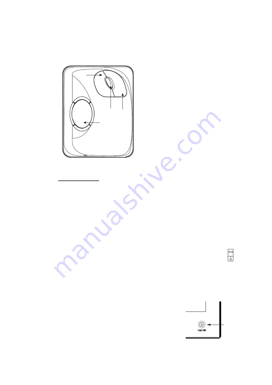
Trackball Control Unit
The Trackball Control Unit consists of a trackball, scrollwheel and left and right mouse
buttons. You operate the unit just like a PC mouse; roll the trackball and operate the
left and right buttons and the scrollwheel to do various functions.
Operator fitness
The operator fitness signal is output whenever the trackball, scrollwheel, right button
or the left button is operated.
1.4
DVD Drive
A USB DVD drive is provided to upload chart data to the system.
The operating temperature range is 5°C(41°F) to 35°C(95°F).
Connect the end of the cable with the USB symbol to a USB port on the
PCU. If the power from the USB port is insufficient, the power lamp on
the drive flashes red. If this occurs, also connect the USB power connec-
tor cable (shown to the right) to the PCU to draw additional power.
1.5
How to Turn the Power On or Off
The power switch on the PCU illuminates in red when
the power is connected and the PCU is turned off. To
turn the power on, push the power switch until the lamp
in the switch illuminates in green.
To turn the power off, press and hold down the power
switch until the power goes off (approx. four seconds).
Left button
• Does the operation related to the object
selected.
• Confirms the operation done for the object
selected.
Scrollwheel
• Selects menu options.
• Selects chart scale.
• Sets numeric data.
• The scrollwheel does not have a “push” func-
tion.
Right button
• Displays context-sensitive menu when cursor
is put in the display area.
• Cancels operation done on the object
selected.
Trackball
• Moves the cursor.
• Selects an object.
Trackball
Right
button
Left
button
Scrollwheel
USB power
connector
POWER
switch
Summary of Contents for FMD3100
Page 36: ...1 INTRODUCTION 1 20 This page is intentionally left blank ...
Page 70: ...2 OPERATIONAL OVERVIEW 2 34 This page is intentionally left blank ...
Page 128: ...5 VECTOR S57 CHARTS 5 12 This page is intentionally left blank ...
Page 140: ...7 C MAP BY JEPESSEN CHARTS 7 6 This page is intentionally left blank ...
Page 206: ...11 HOW TO MONITOR ROUTES 11 16 This page is intentionally left blank ...
Page 230: ...13 TRACKED TARGET TT FUNCTIONS 13 10 This page is intentionally left blank ...
Page 244: ...14 AIS TARGET FUNCTIONS 14 14 This page is intentionally left blank ...
Page 250: ...15 AIS SAFETY NAVTEX MESSAGES 15 6 This page is intentionally left blank ...
Page 294: ...19 RECORDING FUNCTIONS PLAYBACK FUNCTIONS 19 14 This page is intentionally left blank ...
Page 312: ...20 ALERTS 20 18 This page is intentionally left blank ...
Page 332: ...22 SETTINGS MENU 22 16 This page is intentionally left blank ...
Page 338: ...23 MAINTENANCE AND TROUBLESHOOTING 23 6 This page is intentionally left blank ...
Page 395: ......


