iii
TABLE OF CONTENTS
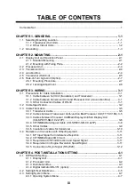
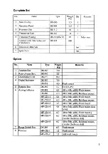
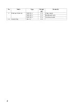
Complete Set ........................................................................................................................ 1
Installation Materials ............................................................................................................. 3
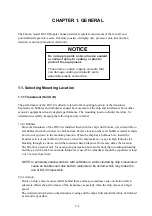
CHAPTER 1. GENGERAL ................................................................................. 1-1
1.1 Selecting
Mounting Location ...................................................................................... 1-1
1.1.1 Transducer (Hull Unit) ..................................................................................... 1-1
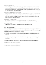
1.1.2 Other Indoor Units ........................................................................................... 1-2
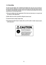
1.2 Grounding.................................................................................................................. 1-3
CHAPTER 2. MOUNTING.................................................................................. 2-1
2.1 Display Unit and Operation Panel .............................................................................. 2-1
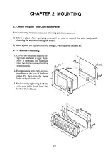
2.1.1 Standard Mounting .......................................................................................... 2-1
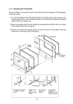
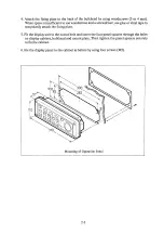
2.1.2 Mounting with Fixing Plate............................................................................... 2-2
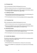
2.2 Processor
Unit ........................................................................................................... 2-4
2.3 Transceiver Unit......................................................................................................... 2-4
2.4 Junction
Box .............................................................................................................. 2-4
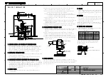
2.5 Transducer
(Hull Unit)................................................................................................ 2-5
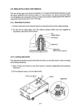
2.6 Rate-of-Turn
Gyro Unit (Option)................................................................................. 2-7
2.6.1 Mounting Procedure ........................................................................................ 2-7
2.6.2 Leveling
Adjustment ........................................................................................ 2-8
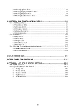
CHAPTER 3. WIRING ........................................................................................ 3-1
3.1 Precautions
for
Cable Installation............................................................................... 3-1
3.1.1 Cable between hull Unit (transducer) and Transceiver .................................... 3-1
3.1.2 Cable between transceiver Unit and Processor Unit (via Junction Box)........... 3-1
3.1.3 Other Connection Cables of DS-30 ................................................................. 3-1
3.2 Cable
Specification .................................................................................................... 3-2
3.3 Cable
Fabrication....................................................................................................... 3-5
3.3.1 Transducer Cable ............................................................................................ 3-5
3.3.2 Cables between Transceiver Unit/Junction Box/Processor Unit (TTYCY-16S). 3-5
3.3.3 Cables between Processor Unit/Main Display Unit/Sub Display Unit
(CO-SPEVV-SB-C
0.2x10P)............................................................................ 3-6
3.3.4 CIF/NMEA Data Signal Cable (CO-SPEVV-SB-C 0.2x5P)............................... 3-8
3.3.5 Other Cables ................................................................................................... 3-9
3.3.6 Insulation
of cables for transducer................................................................. 3-10
3.4 Remarks on Connection with Other Equipment........................................................ 3-11
3.4.1 KP Input Signal for Interference Rejection ..................................................... 3-11
3.4.2 CIF/NMEA Signal I/O Circuit.......................................................................... 3-11
3.4.3 Requirement of Wind Direction and Speed Signal ......................................... 3-11
3.4.4 Requirement in Engine Revolution Speed Signal........................................... 3-11
3.4.5 Connection
of Gyro
Signal (RS-232C)........................................................... 3-12
CHAPTER 4. POST-INSTALLATION SETTING ................................................ 4-1
4.1 DIP
Switch Setting ..................................................................................................... 4-1
4.1.1 Display Unit ..................................................................................................... 4-1
4.1.2 Processor Unit................................................................................................. 4-2
4.1.3 Distribution Box ............................................................................................... 4-3
4.1.4 Digital Indicator DS-351 (option)...................................................................... 4-4
4.2 Setting
Offset
Data Menu........................................................................................... 4-5
4.3 Setting
System Menu................................................................................................. 4-7
4.3.1 Opening System Menu .................................................................................... 4-7
Summary of Contents for DS-30
Page 3: ......
Page 7: ......
Page 11: ......
Page 12: ......
Page 13: ......
Page 14: ......
Page 15: ......
Page 18: ......
Page 19: ......
Page 20: ......
Page 21: ......
Page 22: ...3 3 ...
Page 23: ......
Page 24: ......
Page 25: ......
Page 31: ......
Page 32: ......
Page 33: ......
Page 34: ......
Page 35: ......
Page 36: ......
Page 37: ......
Page 38: ......
Page 39: ......
Page 40: ......
Page 41: ......
Page 43: ......
Page 44: ......
Page 45: ......
Page 46: ......
Page 47: ......
Page 48: ......
Page 49: ......
Page 50: ......
Page 51: ......
Page 52: ......
Page 53: ......
Page 54: ......
Page 55: ......
Page 56: ......
Page 57: ......
Page 58: ......
Page 59: ......
Page 60: ......
Page 75: ...Sep 29 05 D 2 ...
Page 76: ......
Page 77: ......
Page 78: ...Y Hatai D 5 ...
Page 79: ...D 6 ...
Page 80: ......
Page 81: ...23 Oct 08 R Esumi D 8 ...
Page 82: ...Y Hatai D 9 ...
Page 83: ...H HAYASHI Feb 12 04 D 10 ...
Page 84: ......
Page 85: ......
Page 86: ...Feb 22 05 D 13 ...
Page 87: ......
Page 88: ......
Page 89: ......
Page 90: ...H HAYASHI Feb 12 04 D 17 ...
Page 91: ...Jan 07 06 D 18 ...
Page 92: ...Jan 07 06 D 19 ...
Page 93: ......
Page 94: ......
Page 95: ......
Page 96: ......
Page 97: ......
Page 98: ......
Page 99: ......
Page 100: ......
Page 101: ...May 20 04 D 28 ...
Page 102: ...D 29 ...
Page 103: ...D 30 ...
Page 104: ...D 31 ...
Page 105: ...D 32 Sep 29 05 D 34 ...
Page 106: ...D 33D 35 ...
Page 109: ......
Page 110: ......
Page 111: ......
Page 112: ......
Page 113: ......
Page 115: ......
Page 116: ......


