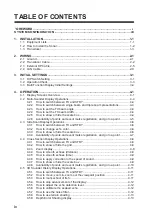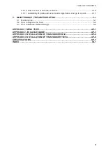
2. WIRING
2-4
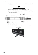
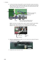
8. Referring to the interconnection diagram (at the back of this manual) and the illus-
tration below, connect the transducer cable to WAGO connectors. (The WAGO
connector opener is provided inside the unit. See the figure at step 4 for the loca-
tion.)
9. Reattach the WAGO connectors.
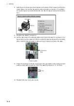
10. Set the cable where the clamping plate was removed (at step 6). As shown in the
figure below, lay the cable such that its conductive tape lies beneath the clamping
plate. Hold the clamping plate in place with your fingers then fasten the plate.
11. Fasten the sealing nut into the super gland. The gap between the sealing nut end
and the super gland should be 2 mm. The fastening torque is 1.8 - 2.0 N•m.
12. Reattach the inner and outer covers.
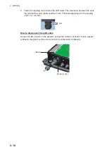
How to connect cable to WAGO connector
Push down
Opener
WAGO
connector
Wire
Twist
<Procedure>
1. Twist core.
2. Insert opener in hole and
push down.
3. Insert core into hole.
4. Release opener.
5. Tug on wire to confirm tight
connection.
Clamping plate
Conductive
tape
2 mm
Summary of Contents for DFF-3D
Page 1: ...MULTI BEAM SONAR DFF 3D OPERATOR S MANUAL www furuno com Model ...
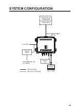
Page 10: ...SYSTEM CONFIGURATION viii This page is intentionally left blank ...
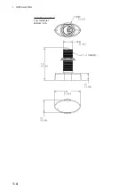
Page 14: ...1 INSTALLATION 1 4 Unit of measurement Top millimeter Bottom inch ...
Page 16: ...1 INSTALLATION 1 6 This page is intentionally left blank ...
Page 36: ...3 INITIAL SETTINGS 3 10 This page is intentionally left blank ...
Page 54: ...4 OPERATION 4 18 This page is intentionally left blank ...
Page 68: ...APPENDIX 4 INSTALLATION OF TRANSDUCER TM54 AP 12 This page is intentionally left blank ...
Page 71: ...D 1 20 Sep 2016 H MAKI 20 Sep 2016 H MAKI 20 Sep 2016 H MAKI 20 Sep 2016 H MAKI ...
Page 74: ...INDEX IN 2 Z Zoom display 4 8 ...

