


BX-7300 • 180403
© www.funkamateur.de
13
Control cables
Automatic Antenna Selector
Assembly of the control
cables
For the first section we haven’t needed the cable, neverthe-
less now that all the soldering work has been completed it is
reasonable that it is prepared now. There are some special
plug connections to make. In the kit there is a 13 pole DIN
socket and a cable with a mini DIN plug attached at one end.
N.B.
For a later connection of a CAT interface an ordinary
(stereo) audio cable with a 3.5mm jacke plug may be used.
Such cables are usually to be found in most shacks. The
cable should be screened to avoid receive breakthrough on
the CAT interface.
Most modern Icom transceivers are are furnished on the rear
panel with a 13 pin DIN socket (ACC) with a uniform pin
layout. On this basis the plug layout in picture 29 can be ap-
plied to most transceivers. A moment to check and verify
with the handbook should enable the correct fabrication of
the cable. It should be fairly easy to assemble the supplied
13 pole DIN plug and the cable with the 6 pole mini DIN
plug.
Older Icom transceivers come with 7 and/or 8 pole ACC
sockets, the socket connections are in the handbook.
We must find the pins for the line voltage, transmit/receive
switching, operating voltage
(13.8V) and earth. Such plug connectors are available at e.g.
[2].
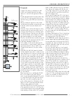
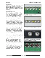
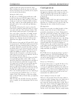
Picture 29. Example of the plug layout of the connecor cables be-
tween the FA- AS and Icom transceiver.
5 (bl)
3 (ye)
1 (red)
2 (br)
8 (ye)
3 (br)
SEND
2 (red)
GND
5 (bl)
BAND
isolate
remaining
wires
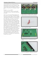
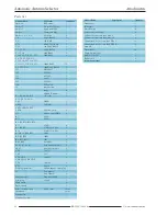
Picture 30.
Connection of the FA -AS to
an Icom trans ceiver.
Antenna Selector FA-AS
A1
TRX-ACC
TRV
A4
A3
A2
A1
TRX
Transverter
RX
CI-V
CAT
Data
Line
voltage,
(H)SEND,
+13,8V
A2
A3
A4
TRV
ACC
Remote
Antenna
IC-7300
With the soldering and assembly of the cable one must be-
ware of careless shortcircuiting between the connections.
Certainly this would only send DC in the direction of the
FA-AS but nevertheless should be done carefully. If the
ACC socket is set up for another peripheral apparatus then a
so called ‘Y’ cable must be installed with a plug and two
parallel connected sockets at the ends. A parallel circuit of
the ensemble is in principle not critical. The maximum load
on the 13.8V pins of the ACC socket is given as 1A (see
handbook). The FA-AS takes a maximum of 0.1A so that
parallel connected apparatus shouldn’t take more than 0.9A.
In the event that the power supplied by the transceiver is not
wanted then alternatively batteries or DC supply to socket 7
are possible. However it should be noted that the FA-AS has
no independent on/off switch so that this would need to be
switched externally.
Summary of Contents for BX-7300
Page 20: ...BX 7300 February 2018...


