
1-10-1
E9703FIS
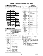
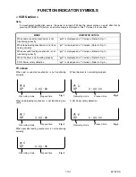
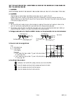
FUNCTION INDICATOR SYMBOLS
< VCR Section >
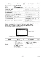
Note:
If a mechanical malfunction occurs, the power is turned off. When the power comes on again after that by
pressing [STANDBY-ON] button, an error message is displayed on the TV screen for 5 seconds.
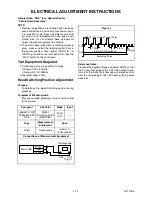
TV screen
When reel or capstan mechanism is not functioning
correctly
When tape loading mechanism is not functioning cor-
rectly
When cassette loading mechanism is not functioning
correctly
When the drum is not working properly
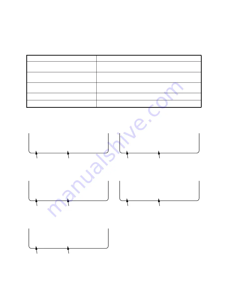
P-ON Power safety detection
MODE
INDICATOR ACTIVE
When reel or capstan mechanism is not
functioning correctly
“
A
R” is displayed on a TV screen. (Refer to Fig. 1.)
When tape loading mechanism is not func-
tioning correctly
“
A
T” is displayed on a TV screen. (Refer to Fig. 2.)
When cassette loading mechanism is not
functioning correctly
“
A
C” is displayed on a TV screen. (Refer to Fig. 3.)
When the drum is not working properly
“
A
D” is displayed on a TV screen. (Refer to Fig. 4.)
P-ON Power safety detection
“
A
P” is displayed on a TV screen. (Refer to Fig. 5.)
A
R
SP 0 : 00 : 00
Recording mode
Elapsed time
Fig. 1
A
T
SP 0 : 00 : 00
Recording mode
Elapsed time
Fig. 2
A
C
SP 0 : 00 : 00
Recording mode
Elapsed time
Fig. 3
A
D
SP 0 : 00 : 00
Recording mode
Elapsed time
Fig. 4
A
P
SP 0 : 00 : 00
Recording mode
Elapsed time
Fig. 5
Summary of Contents for DRV-A2635
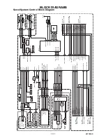
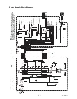
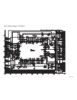
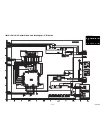
Page 37: ...1 12 3 E9709SCM1 Main 1 9 Schematic Diagram VCR Section...
Page 39: ...1 12 5 E9709SCM3 Main 3 9 Schematic Diagram VCR Section...
Page 40: ...1 12 6 E9709SCM4 Main 4 9 Schematic Diagram VCR Section...
Page 41: ...1 12 7 E9709SCM5 Main 5 9 Schematic Diagram VCR Section...
Page 42: ...1 12 8 E9709SCM6 Main 6 9 Front Jack Schematic Diagram VCR Section...
Page 43: ...1 12 9 E9709SCM7 Main 7 9 Schematic Diagram VCR Section...
Page 44: ...1 12 10 E9709SCM8 Main 8 9 Schematic Diagram VCR Section...
Page 45: ...1 12 11 E9709SCM9 Main 9 9 Schematic Diagram VCR Section...
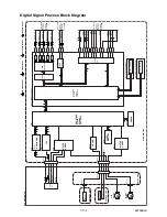
Page 47: ...1 12 13 E9709SCRJ Rear Jack Schematic Diagram VCR Section...
Page 48: ...1 12 14 E9709SCAFV AFV Schematic Diagram VCR Section...
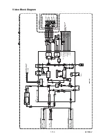
Page 49: ...1 12 15 E9709SCD1 DVD Main 1 6 Schematic Diagram DVD Section...
Page 50: ...1 12 16 E9709SCD2 DVD Main 2 6 Schematic Diagram DVD Section...
Page 51: ...1 12 17 E9709SCD3 DVD Main 3 6 Schematic Diagram DVD Section...
Page 85: ...DRV D2831 E9709ED 2005 10 27...