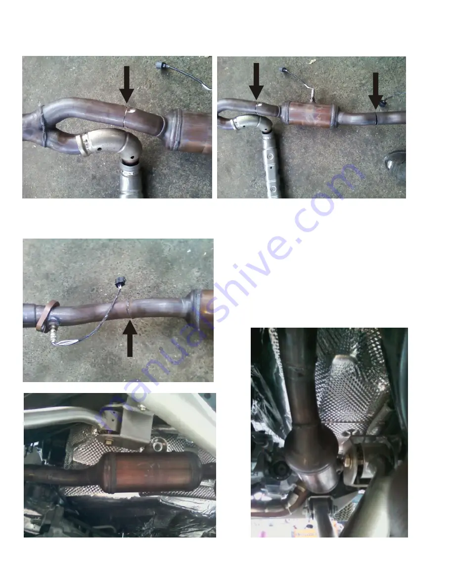
System shown with modifications. Arrows indicate the location to cut,rotate 180 degrees and re-weld to allow for proper clearance.
continued....
Fig.16A
Fig.16
Fig.13
Fig.14
Fig.15
Pg.13
Driver Side on USA models
Page 1: ...Part Number FTS7330 3 0 System 2007 14 JEEP JK SUSPENSION SYSTEM MADE IN THE U S A 4 0 Kit Shown JK LONG ARM 3 0...
Page 2: ...s Alignment Spacer 8 Component Box A QTY Continued 50 710201 JK Front Track Bar Component 1 With Pre installed Rubber eyelet bushing 50 710202 JK Rear Track Bar Component 1 With Pre installed Rubber e...
Page 3: ...Pin threaded 1 2 13 2 U0120677 Bail Pins 4 MOO392 BK 01 5 8 Hourglass Bushing 4 SLE104 1 2 x 1 3 8 Sleeves 4 70 4180 12 Radius Shank Rear Sway Bar Link Kit Assembled 12 30 Degree Radius Shank Rear Sw...
Page 4: ...Installation time will vary NO transfer case or exhaust modifications are required for 2007 2009 or 2012 You ve made a purchase of the best suspension system available For a correctly installed system...
Page 5: ...Suspension systems or components that enhance the off road performance of your vehicle may cause it to handle differently on and off road than it did from the factory Care must be taken to prevent los...
Page 6: ...l save installation time Always wear safety glasses when using power tools A Jeep Wrangler JK Factory Service manual will aide in the installation of this kit DISASSEMBLY FRONT 1 Raise and support veh...
Page 7: ...installers may want to change the order of installation procedures to suit their needs INSTALL FRONT BUMP STOPS Perform the work to the vehicle doing one side of the vehicle at a time We will start o...
Page 8: ...tion Fig 1 6 Support the front axle assembly Remove both upper and lower control arms from both sides of vehicle You are preparing the area to remove the brackets from the frame 7 Next remove front lo...
Page 9: ...Drill 3 8 hole from inside these holes to outside of frame Do not use this hole NOT USED Finish grinding off remaining metal as shown Fig 4 Pg 9...
Page 10: ...toff wheel cut around the base of the upper mount Here we have used a plasma cutter to remove mount An electric grinder or die grinder w cut off wheel will work Grind area completely flat to frame rai...
Page 11: ...ck nuts Install 3 8 bolts from the inside of the frame as shown Mount the Lower 9 16 x 1 5 bolt as shown The red arrow indicates the frame access hole for the nut tab to be inserted for the bottom bol...
Page 12: ...crush sleeve Once they are all tight loosen the one with the crush sleeve for later when the skid plate is installed 5 Complete rear mount assembly and reinstall gas tank Note Refer to page 25 for al...
Page 13: ...tem shown with modifications Arrows indicate the location to cut rotate 180 degrees and re weld to allow for proper clearance continued Fig 16A Fig 16 Fig 13 Fig 14 Fig 15 Pg 13 Driver Side on USA mod...