


7. OPERATIONS - BASIC LEVEL
9. HUMIDITY CONTROL ADJUSTMENT
10. OPERATIONS - ADVANCED LEVEL
9.1 Operating modes of humidity control
The
TO751B
allows control of humidity inside the dough proofer in two different ways: One is reading the indoor
environment using a temperature and humidity sensor (SB56) or by using only a dedicated cyclic timer that
allows on-and-off time adjustments of humidity output control without use a humidity sensor. In this way, it is
possible to maintain a higher humidity level during any process step through function
[F08]
- Humidity
control operating mode
, it allows the humidity control only operates in the heating mode (manual or automatic),
only in the cooling process (manual or automatic) or in both heating and cooling processes (manual or
automatic). Function
[I01]
- Enables the humidity
sensor to enable or not to activate the humidity sensor, and
with this the respective humidity control mode.
9.2 Adjustment of the cyclic timer of the humidity output (with SB56 temperature
sensor)
The standard sensor used in the controller is the SB41 model, which performs only temperature measurements.
However, an exclusive cyclic timer can be used to control the moisture inside the chamber for the fermentation
process. By adjusting the on and off time values it is possible to toggle the status of the humidity output. To set the
cyclic timer values, press the
>
key for 4 seconds while the main display of the controller is displayed, until the
message
[,,5] [,ton]
(time on) is displayed, indicating that the time can be set the humidity output will
remain activated using the
<
or
>
keys and after the setting, press the key (short touch) to confirm the desired
value. In the sequence, the message
[,60]
[tOFF]
(time off) will be displayed, indicating that the time that the
humidity output will be deactivated can be adjusted using the
<
or
>
keys and after setting, press the key ( short
press) to confirm the value. In this way the humidity output will be activated respecting the times set in
[,ton]
and
[tOFF]
during the respective processing mode according to the setting made in function
[F08]
.
If it is not necessary to use the humidity output, the output can be deactivated by moving the parameter setting
[,ton]
to the minimum until the display shows
[no,]
.
9.3 Humidity setpoint adjustment (with SB56 humidity sensor)
If you want to perform temperature and humidity measurement, use the SB56 sensor (sold separately) and enter
the function
[i01]
- Enable the humidity sensor in the installation menu and select
[,YES]
. In this way, it will
be possible to control the humidity of the fermentation chamber during its process, as adjusted in function
[F08]
. To set the humidity setpoint value, press the
>
key for 4 seconds during the main controller display until
[50.0] [SPHu]
is displayed, indicating that the desired value can be set within the limits defined in
[F10]
-
Minimum value allowed to set the humidity setpoint and
[F11]
- Maximum value allowed to set the humidity
setpoint, using the
<
or
>
keys. After setting, press the key (short key) to confirm the saved value.
SET
SET
SET
SET
8. CLOCK AND DAY OF THE WEEK ADJUSTMENT
SET
SET
SET
10.2 Parameters table
SET
[CoD]
0
9999
-
0
[F01]
-5.0
(-9)
5.0
(9)
°C
(°F)
0.0
(0)
[F02]
-9.9
(14)
F03
°C
(°F)
4.0
(39)
[F03]
F02
70.0
(158)
°C
(°F)
15.0
(59)
-
[SnG2]
Single mode with refrigeration at the end of the cycle: The controller will control the refrigeration of the
oven before the time to start the fermentation cycle and after the end of the cycle. After the end time of the
fermentation cycle, however, the automatic control will be switched off and the controller will be in manual
refrigeration mode, i.e. if required, the user must activate the automatic mode again to perform a new
fermentation cycle, observing the days selected in function
[CYC]
in the user’s manu.
NOTE:
If mode
[Cont]
is selected, the controller will control the refrigeration before and after the end of the
fermentation cycle, observing the days selected for the fermentation cycles in accordance with the value of
function
[CYC]
. Example:
Fermentation cycle start and end times -
[Ini]
: 02:00 / Time to end the fermentation cycle -
[end]
: 06:00 /
Cycle type -
[CYC]
:
[,ter]
/ Process mode -
[F12]
=
[Cont]
.
Each fermentation cycle will start on Tuesday at 02:00 and end at 06:00, but since it is configured for one day only,
however in continuous mode, the controller keep refrigerating in automatic mode until the following Tuesday, at
02:00 or until the user disables the automatic mode or changes the schedule.
6.3.2 Manual mode
You can switch between manual heating mode or manual refrigeration mode, thus the user is responsible for
changing the operating mode when needed or activating the automatic mode. If the controller is in manual mode,
the respective mode configurations, like setpoint and hysteresis, will be observed. The start and end times of the
fermentation cycle, however, will not be observed when the manual mode is configured, but only in automatic
mode. When heating mode is selected, the message
[mod]
[HEAt]
will be displayed and when refrigeration
mode is selected, the message
[mod]
[rEFr]
will be displayed.
6.3.3 Control mode off
It is possible to switch off the control functions together with all the controller's outputs. When the control mode is
switched off, the message
[mod]
[,OFF]
will be displayed, indicating the controller will no longer activate the
outputs, i.e. the environment control of the rising oven is disabled.
6.4 Magnitude views
6.4.1 Three-digit display
In the standard mode (with temperature sensor only), the upper display will show only the value measured by the
temperature sensor.
If the humidity sensor is enabled, the upper, three-digit display will alternate between the display of the legend of
the respective magnitude and the value measured by the sensors, as follows:
The display will show the legend
[TMP]
and then, after a few moments, the temperature measured by the
sensor, for instance
[25.0]
, along with the indication of the respective LED of the temperature units.
After that, the display will show the legend
[HuM]
and then, after a few moments, the relative humidity measured
by the sensor, for instance
[70.0]
.
6.4.2 Four-digit display
The lower, four-digit display will show the real time clock for about 10 seconds, switching to the day of week for
about four seconds.
SET
SET
SET
SET
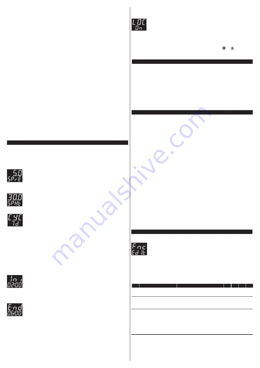
The controller offers easy access to the resources relevant to the user of the rising oven, allowing adjusting the
refrigeration setpoint
[SPrE]
, heating setpoint
[SPHt]
, cycle type
[CYC]
, cycle start time
[Ini]
and cycle
end time
[End]
. To access the user menu, press (quick touch) and adjust the parameters as follows:
7.1 Refrigeration setpoint adjustment
SET
The display will keep flashing the refrigeration setpoint value while it is being adjusted, observing
the limits set on
[F02]
– Minimum value allowed to configure the refrigeration setpoint, and
[F03]
– Maximum value allowed to configure the refrigeration setpoint. The value is adjusted
using
<
or
>
and the desired value is confirmed with a quick touch on .
7.2 Heating setpoint adjustment
SET
The display will keep flashing the heating setpoint value while it is being adjusted, observing the
limits set on
[F05]
– Minimum value allowed to configure the heating setpoint, and
[F06]
–
Maximum value allowed to configure the heating setpoint. The value is adjusted using
<
or
>
and the desired value is confirmed with a quick touch on .
7.3 Cycle type adjustment
After confirming the adjustment of the refrigeration and heating setpoints, the message
[CYC]
will be displayed to allow adjusting the type of cycle in accordance with the following options:
[,7d,]
- All days of the week;
[,D0m]
- Sunday only;
[,SeG]
- Monday only;
[,Ter]
- Tuesday only;
[,Qua]
- Wednesday only;
[,Qui]
- Thursday only;
[,SeH]
- Friday only;
[,Sab]
- Saturday only;
After selecting the type of processing cycle, you must confirm the selection with a quick touch on to save this
value and proceed to the adjustment of the cycle start and end times;
7.4 Adjustment of the start time of the fermentation cycle
Here you must select the time of the day to start the fermentation process. First the two digits
corresponding to the hours will flash indicating that you must adjust the hours using
<
or
>
and
confirm the adjustment with a new touch on . After that the last two digits will start to flash
indicating that you must now adjust the minutes using
<
or
>
and confirm the adjustment with a
new touch on to save the time adjustment to the controller's memory.
7.5 Adjustment of the end time of the fermentation cycle
Now you must adjust the time to end the fermentation process. First the two digits corresponding
to the hours will flash indicating that you must adjust the hours using
<
or
>
and confirm the
adjustment with a new touch on . After that the last two digits will start to flash indicating that
you must now adjust the minutes using
<
or
>
and confirm the adjustment with a new touch on
DDD
to save the adjustment to the controller's memory.
SET
To access the clock adjustment menu, press
<
for four seconds while the temperature and clock are being
displayed until the message
[ClO][00:00]
appears on the display, where the first two digits will flash,
indicating you can adjust the hours using
<
or
>
, then press (quick touch) to save. After that, the time setting
is saved and the last two digits will flash, indicating you can adjust the minutes using
<
or
>
then save the clock
setting by pressing (quick touch). Now the display will show
[dAY][,dOM]
indicating you can adjust the
day of the week using
<
or
>
and confirm the adjustment by pressing (quick touch). In this way the time has
been adjusted and saved to the controller's internal RTC. The messages with the day of the week will be
displayed according to the language selected in
[i03]
.
NOTE:
The controller has an auxiliary internal power supply to keep the clock running for at least 72 hours in case
of power fault. If the controller remains off for a long period of time, the message
[ECLO]
, may be displayed to
indicate that the clock is not programmed. In this case, the date and time must be adjusted and the controller must
be kept on for 10 hours to fully recharge the auxiliary power supply.
7.6 Functions lock
To enable / disable the function lock, press
<
and
>
and hold for the time configured in
parameter
[F18]
- Time for function lock.
When this configuration is active, the parameters cannot be changed, but they can be viewed.
When the lock is active, the parameters available for adjustment are defined in parameter
[F17]
– Functions Lock.
Icon
&
indicates the status of the lock. Icon lit indicates the functions lock is active.
7.7 Enable the Default operation mode of the level sensor input
If an error occurs in the tank level sensor, you can ignore the error message
[Er5]
, but then the controller will no
longer monitor the water level, resulting in an operation with reduced safety. To ignore the error
[Er5]
and
operate without level sensor measurement, the controller must be powered on with and
pressed until the
R
HE
message
[SnS][,OFF]
appears on the display. In this way, the tank level control will be disabled until the
controller is restarted.
10.1 Changing the controller parameters
Access the advanced configuration menu by pressing the key for 4 seconds until
[Fnc]
is
displayed. When
[CoD]
, is displayed, press
again (quick touch). Use the
<
or
>
to enter
DDI
the access code 123 and then press
(quick touch) again.
DDI
SET
SET
Use the
<
or
>
keys to select the desired function. The value can be edited with a quick touch on the key.
Use the
<
or
>
keys to change the value and press the key with a quick touch when ready to save the
configured value and return to the functions menu.
To leave the configuration menu and return to the normal operating mode (temperature and time indication),
press (long touch) until
[----]
is displayed.
DESCRIPTION
FUN
MIN MAX UNIT DEF.
FUNCTION
Access code (123)
Temperature sensor
indication offset
Required when you want to change the
advanced configuration parameters.
Minimum value allowed to
configure the refrigeration
setpoint
Maximum value allowed to
configure the refrigeration
setpoint
Allows compensating for deviations in the
sensor temperature reading.
These parameters serve as the lower and
upper threshold for the adjustment of
parameter
[SPrE]
- refrigeration
setpoint. They are used to block
temperature adjustment and avoid an
improper configuration for the operation.


