


FLASH PROGRAMMER YOKOGAWA AF220/221
Introduction
© Fujitsu Microelectronics Europe GmbH
- 9 -
MCU-AN-390087-E-V10
4.4 Target
Probe
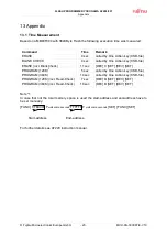
The AF220/221 Flash Programmer uses a rare connector for connection to the target board:
DX31A-28P/DX-28-CV from Hirose Electric (
www.hirose.com
)
Figure 1-7: Pin Layout of
Target Probe Connector
Figure 1-8: Pin Layout of Target Probe
Connector viewed from cable side
Yokogawa offers optional three types of Probe Cables (Interface Cable). Depending on the
target board a cable with connector on both sides, with test clip on one side or a
simple cable has to be ordered:
Figure 1-9: Interface Cable AZ210
Figure 1-10: Interface Cable
AZ211
Figure 1-11: Interface Cable AZ212
AZ211
AF220 -
Signal Name
AZ210 / AZ212
Pin No.
Pin No.
color
Fujitsu-Name
TRXD 27
1
brown
SOTx
*1
TTXD 13
2 red
SINx
*1
TCK
6
12
white & red
SCKx
*1
TAUX 23
9
white
P00
*2
-
-
-
-
P01
*2
TMODE 12
4 yellow
MD0
TAUX4
20
11
white & brown
MD1
TAUX3
19
13
white & orange
MD2
/TRES
5
14
white / yellow
/RST
/TICS 10
8 grey
optional
*3
TVCC 2 20
light
blue
Vcc
VCC
3
18
white & grey
Vcc
GND
1,7,8, 14, 15, 21, 22, 28
soldered on PCB
(black) GND
Table 1-1: Signal assignment of interface cable
*1
The used serial interface depends on the microcontroller series.
*2
Instead of P00, P01 other port-pins may be used
(See to Application-Note AN-MCU-390031-E-xx)
*3
The programmer signals (SINx, SOTx, SCKx, P00, P01, \RST) may conflict with the user-
system while programming. The signal /TICS can be used to disconnect the user circuit but additional three-state
drivers have to be used. Refer to the chapter “Examples of serial programming connection” of the MCU
hardwaremanual.


