


50
Operating Manual
RX2530 M4
Hardware installation
Some standard connectors are color-coded.
Figure 4: Connectors on the rear
I
Some of the devices that can be connected may require the installation
and setting up of special software (e.g. drivers) (see the documentation
for the connected device).
I
Shared LAN connector is displayed in the BIOS Setup Utility and on the
MAC address label as LAN2. Standard LAN connector is displayed in the
BIOS Setup Utility and on the MAC address label as LAN1.
Note for LAN connectors on OCP modules
The LAN connectors on the OCP modules are numbered in ascending order
from right to left beginning with “0”.
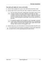
Ê
Connect the desired devices to the server.
Pos. Description
1
USB 3.0 connector
2
OCP module (optional, different variants)
3
USB 3.0 connector
4
Management LAN connector (for iRMC S5 server management
function)
5
Shared LAN connector (LAN1)
6
LAN connector (LAN2)
7
Video connector (VGA)
Summary of Contents for PRIMERGY RX2540 M4
Page 1: ...Operating Manual English FUJITSU Server PRIMERGY RX2530 M4 Operating Manual July 2017 ...
Page 8: ...Operating Manual RX2530 M4 Contents ...
Page 12: ...12 Operating Manual RX2530 M4 Introduction ...
Page 30: ...30 Operating Manual RX2530 M4 Functional overview ...
Page 78: ...78 Operating Manual RX2530 M4 Starting up and operation ...
Page 80: ...80 Operating Manual RX2530 M4 Property and data protection ...