background image

42

Options Guide

 BX400 

S1

Conversion from a rack model to a floorstand model

©

 c

o

gn

it

a

s

. Ge

s

e

lls

c

h

ft

 f

ü

r T

e

c

h

ni

k

-Do

k

u

m

ent

a

ti

o

n m

b

H

 2

0

1

0


P

fad

: C

:\

P

ro

gram

m

e

\F

C

T

\t

im

_ap

p\

ti

m

_

lo

c

a

l\

wo

rk

\W

A

LT

E

R\

OB

J

_

D

O

K

U

-9

4

72-

0

01

.f

m

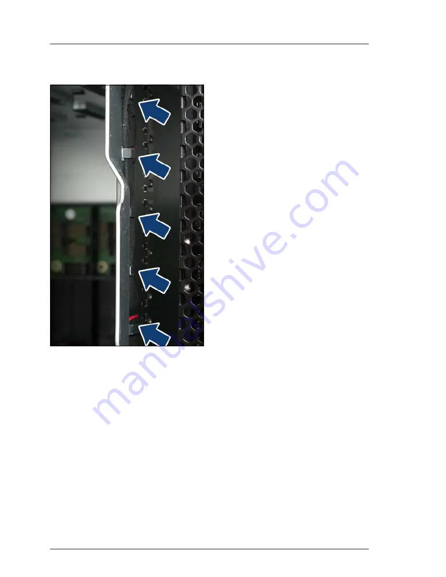
Removing the SATA cable

Figure 27: Removing the SATA cable

Ê

Detach the SATA cable from the 
cable guides inside the FSIOM bay 
(see arrows). 

Summary of Contents for PRIMERGY BX400 S1

Page 1: ...Options Guide English PRIMERGY BX400 S1 System Unit Options Guide December 2010 ...

Page 2: ...entation mbH 2010 Pfad C Programme FCT tim_app tim_local work WALTER OBJ_DOKU 9460 001 fm Copyright 2010 Fujitsu Technology Solutions GmbH All rights reserved Delivery subject to availability right of technical modifications reserved All hardware and software names used are trademarks of their respective manufacturers The contents of this manual may be revised without prior notice Fujitsu assumes ...

Page 3: ...components beyond their operating life may result in electrolyte leakage or depletion potentially causing emission of foul odor or smoke As a guideline in a normal office environment 25 C operating life is not expected to be reached within the maintenance support period 5 years However operating life may be reached more quickly if for example the product is used in a hot environment The customer s...

Page 4: ... follows the guidelines of Voltage Dip Immunity of Personal Computer issued by JEITA the Japan Electronics and Information Technology Industries Association Technology controlled by the Foreign Exchange and Foreign Trade Control Law of Japan Documents produced by Fujitsu may contain technology controlled by the Foreign Exchange and Foreign Trade Control Law of Japan Documents which contain such te...

Page 5: ...onventions 9 2 Procedure 11 3 Safety instructions 13 4 Preparation 21 4 1 Floorstand model 21 4 1 1 Opening the system unit 21 4 2 Rack model 22 5 Optical Disk Drive ODD 23 5 1 Rack model 24 5 2 Floorstand model 26 6 ServerView Local Service Display for Blade 31 7 Conversion from a rack model to a floorstand model 37 8 Completion 57 8 1 Floorstand model 57 ...

Page 6: ...OptionsGuide BX400 S1 Contents cognitas Gesellschft für Technik Dokumentation mbH 2010 Pfad C Programme FCT tim_app tim_local work WALTER OBJ_DOKU 9461 001 fm 8 2 Rack model 58 Index 59 ...

Page 7: ... performed by technical specialists I The installation and removal of the hot plug components is described in the Operating Manual supplied with the system unit 1 2 Documentation overview More information on your PRIMERGY BX400 S1 system unit can be found in the following documents Quick Start Hardware PRIMERGY BX400 S1 leaflet はじめにお読みください PRIMERGY BX400 S1 for the Japanese market only included as...

Page 8: ...r of the server http primeserver fujitsu com primergy system html The PDF files of the manuals can also be downloaded free of charge from the Internet The overview page showing the online documentation available on the Internet can be found using the URL for EMEA market http manuals ts fujitsu com The PRIMERGY server documentation can be accessed using the Industry standard servers navigation opti...

Page 9: ...actory equipped with the ServerView Local Service Display for Blade Conversion from a rack model to a floorstand model The rack model can be optionally converted to floorstand model using a conversion kit 1 4 Notational conventions The following notational conventions are used in this manual Text in italics indicates commands or menu items Quotation marks indicate names of chapters and terms that ...

Page 10: ...10 OptionsGuide BX400 S1 Introduction cognitas Gesellschft für Technik Dokumentation mbH 2010 Pfad C Programme FCT tim_app tim_local work WALTER OBJ_DOKU 9462 001 fm ...

Page 11: ...ation overview on page 7 are available print the PDF files if required Most importantly you will need the Operating Manual for the system unit Ê Shut the system unit down correctly and disconnect the power cords and open the system unit as described in the chapter Preparation on page 21 Ê Carry out the expansion or upgrade of your system unit as described in the pertinent chapter I Installation an...

Page 12: ...12 OptionsGuide BX400 S1 Procedure cognitas Gesellschft für Technik Dokumentation mbH 2010 Pfad C Programme FCT tim_app tim_local work WALTER OBJ_DOKU 9463 001 fm ...

Page 13: ...son who is trained to install the server including hardware and software Repairs to the device that do not relate to CSS failures shall be performed by service personnel Please note that unauthorized interference with the system will void the warranty and exempt the manufacturer from all liability Any failure to observe the guidelines in this manual and any improper repairs could expose the user t...

Page 14: ...ly in the original packaging or in packaging that protects it from knocks and jolts Installation and operation V CAUTION This unit should not be operated in ambient temperatures above 35 C If the unit is integrated into an installation that draws power from an industrial power supply network with an IEC309 connector the power supply s fuse protection must comply with the requirements for non indus...

Page 15: ...ded Ethernet cabling has to comply with EN 50173 and EN 50174 1 2 standards or ISO IEC 11801 standard respectively The minimum requirement is a Category 5 shielded cable for 10 100 Ethernet or a Category 5e cable for Gigabit Ethernet Route the cables in such a way that they do not create a potential hazard make sure no one can trip over them and that they cannot be damaged When connecting the serv...

Page 16: ...ified personnel Exception CSS components can be replaced The warranty is void if the server is damaged during installation or replacement of system expansions Only set screen resolutions and refresh rates that are specified in the operating manual for the monitor Otherwise you may damage your monitor If you are in any doubt contact your sales outlet or customer service center Before installing rem...

Page 17: ...he screw removed during installation detaching Internal Options in former device position To use a screw of the different kind causes a breakdown of equipment The installation indicated on this note is sometimes changed to the kind of possible options without notice ...

Page 18: ...DVD BD fragments can pierce the cover of the optical drive equipment damage and can fly out of the device danger of injury particularly to uncovered body parts such as the face or neck High humidity and airborne dust levels are to be avoided Electric shocks and or server failures may be caused by liquids such as water or metallic items such as paper clips entering a drive Shocks and vibrations are...

Page 19: ...the CD DVD BD with a soft dry cloth then let it air dry Do not dry the CD DVD BD using devices such as a hair dryer To avoid dust damage and deformation keep the CD DVD BD in its case whenever it is not in use Do not store CDs DVDs BDs at high temperatures Areas exposed to prolonged direct sunlight or near heating appliances are to be avoided I You can prevent damage from the optical drive and the...

Page 20: ...fore installing or removing components with ESDs You must always discharge static build up e g by touching a grounded object before working with such components Any devices or tools that are used must be free of electrostatic charge Wear a suitable grounding cable that connects you to the external chassis of the system unit Always hold components with ESDs at the edges or at the points marked gree...

Page 21: ...1 1 Opening the system unit Ê Terminate all applications and shut down the system unit correctly Ê If your operating system has not switched off the server press the On Off button Ê Pull all power cables out of the power outlet Ê Unlock the door and remove the key Figure 2 Removing the door Ê Pull the hinge pin see circle downward and remove the door ...

Page 22: ...010 Pfad C Programme FCT tim_app tim_local work WALTER OBJ_DOKU 9465 001 fm 4 2 Rack model Ê Terminate all applications and shut down the system unit correctly Ê If your operating system has not switched off the server press the On Off button Ê Pull all power cables out of the power outlet ...

Page 23: ...e ODD V CAUTION When installing the ODD hold it by the side Applying force to the top may cause failures Follow the safety instructions in the chapter Safety instructions on page 13 Figure 3 Preparing the ODD Ê Fasten the engaging hook on the ODD ...

Page 24: ... Rack model The ODD mounting bay is located on the upper front bezel of the system unit Ê Empty the sever blade slots 7 and 8 See the Operating Manual for how to remove server blades storage blades and server blade dummy modules Figure 4 Removing the ODD dummy module Ê Press the green engaging hook up 1 and to the front side of the system unit 2 to remove the ODD dummy module 0 ...

Page 25: ...h the ODD in the bay of the system unit until it engages Ê Reinstall server blades storage blades or server blade dummy modules in slots 7 and 8 see the Operating Manual Ê Connect the system unit to the power outlet and switch it on as described in the chapter Completion on page 57 ...

Page 26: ...ting bay is located on the FSIOM Ê Empty the sever blade slots 7 and 8 See the Operating Manual for how to remove server blades storage blades and server blade dummy modules Figure 6 Disengaging the FSIOM Ê Disengage the lock of the FSIOM 1 and pull it out of the system unit up to the stop 2 I If the FSIOM is hard to unlock press it at the left front vicinity of server blade slots 7 and 8 as you r...

Page 27: ...Disconnect the door sensor cable small circle and the LCD cable large circle from the FSIOM Ê Unlock the FSIOM 1 and pull it out of the system unit completely 2 Figure 8 Removing the ODD dummy module from the FSIOM Ê Unlock the ODD dummy module 1 and remove it from the FSIOM 2 0 0 ...

Page 28: ...work WALTER OBJ_DOKU 9468 001 fm Figure 9 Inserting the ODD in the FSIOM Ê Push the ODD into the bay of the FSIOM until the engaging hook 1 under the metal holder 2 locks in place Figure 10 Connecting the SATA cable to the ODD Ê Connect the other plug of the SATA cable to the port on the ODD see circle and put the cable in the cable clamp 1 0 ...

Page 29: ... small circle and the LCD cable large circle to the FSIOM Ê Disengage the security lock of the FSIOM 1 and push it completely into the system unit 2 The FSIOM clicks into place in its final position Ê Reinstall server blades storage blades or server blade dummy modules in slots 7 and 8 see the Operating Manual Ê Connect the system unit to the power outlet and switch it on as described in the chapt...

Page 30: ...30 OptionsGuide BX400 S1 Optical Disk Drive ODD cognitas Gesellschft für Technik Dokumentation mbH 2010 Pfad C Programme FCT tim_app tim_local work WALTER OBJ_DOKU 9468 001 fm ...

Page 31: ... Display for Blade is an option in the rack model of the BX400 S1 system unit The ServerView Local Service Display for Blade is placed in the FSIOM instead of the front control panel I The floorstand model is factory equipped with the ServerView Local Service Display for Blade Ê Empty the sever blade slots 7 and 8 See the Operating Manual for how to remove server blades storage blades and server b...

Page 32: ...hnik Dokumentation mbH 2010 Pfad C Programme FCT tim_app tim_local work WALTER OBJ_DOKU 9617 001 fm Figure 13 Disengaging the FSIOM Ê Disengage the lock of the FSIOM 1 and pull it out of the system unit up to the stop 2 I If the FSIOM is hard to unlock press it at the top front as you release it 0 ...

Page 33: ...nplug the SATA cable 1 Ê Unlock the FSIOM 2 and pull it out of the system unit completely Figure 15 Removing the front control panel carrier from the FSIOM Ê Unplug the LCD cable from the front control panel see circle Ê Unlock the carrier of the front control panel 1 and remove it from the FSIOM 2 0 0 ...

Page 34: ... 16 Removing the front control panel from the carrier Ê Remove the stopper from the carrier To do this loosen the screw 1 and push the stopper 2 out Ê Remove the front control panel from the carrier 3 Figure 17 Inserting the ServerView Local Service Display for Blade into the carrier Ê Push the ServerView Local Service Display for Blade into the carrier and secure the stopper with the screw again ...

Page 35: ...ier all the way to the stop into the FSIOM 1 In this position the lock engages 2 Ê Disengage the locking mechanism of the ServerView Local Service Display for Blade 3 and slide it completely into the FSIOM Figure 19 Inserting the carrier into the FSIOM Ê Place the LCD cable in the cable reel 1 Ê Connect the LCD cable see circle 0 1 ...

Page 36: ... the FSIOM into the system unit until the security lock engages Ê Connect the SATA cable see circle Ê Disengage the security lock of the FSIOM 1 and push it completely into the system unit 2 The FSIOM clicks into place in its final position Ê Reinstall server blades storage blades or server blade dummy modules see the Operating Manual Ê Connect the system unit to the power outlet and switch it on ...

Page 37: ... blades and storage blades the connection blades power supply units fan units and management blades in the system unit for reinstallation Ê Remove the server blades storage blades power supply units fan units connection blades and management blades from the system unit For assembly instructions see the Operating Manual Removing the ODD or ODD dummy module Figure 21 Removing the ODD Ê Press the gre...

Page 38: ...mbH 2010 Pfad C Programme FCT tim_app tim_local work WALTER OBJ_DOKU 9472 001 fm Ê Store the ODD or ODD dummy module in a safe place You will need it for installing on the FSIOM later on Removing the handles bars Figure 22 Removing the handle bars Ê Loosen the four countersunk screws on either side to remove the handle bars ...

Page 39: ...to a floorstand model Removing the ID card Figure 23 Pulling the ID card up to the stop Ê Pull the ID card out of the system unit up to the stop Figure 24 Removing the ID card Ê Press the the engaging lug 1 as you pull the ID card out of the system unit 2 0 ...

Page 40: ...okumentation mbH 2010 Pfad C Programme FCT tim_app tim_local work WALTER OBJ_DOKU 9472 001 fm Removing the FSIOM Figure 25 Disengaging the FSIOM Ê Disengage the lock of the FSIOM 1 and pull it out of the system unit up to the stop 2 I If the FSIOM is hard to unlock press it at the top front as you release it 0 ...

Page 41: ...BX400 S1 Options Guide 41 Conversion from a rack model to a floorstand model Figure 26 Removing the FSIOM Ê Unplug the SATA cable 1 Ê Unlock the FSIOM 2 and pull it out of the system unit completely 0 ...

Page 42: ... model cognitas Gesellschft für Technik Dokumentation mbH 2010 Pfad C Programme FCT tim_app tim_local work WALTER OBJ_DOKU 9472 001 fm Removing the SATA cable Figure 27 Removing the SATA cable Ê Detach the SATA cable from the cable guides inside the FSIOM bay see arrows ...

Page 43: ...m unit by loosening the two countersunk screws see circles Figure 29 Removing the SATA cable Ê Detach the plug from the fixing pins see circles Ê Detach the cable from the cable guides see arrows Ê Carefully pull out the other end of the cable of the hole in the system unit Ê Store the cable in a safe place You will need it for the connection of the ODD on the FSIOM later on ...

Page 44: ...nt control panel from the FSIOM Ê Unplug the LCD cable from the front control panel and from the FSIOM see circles and remove the LCD cable by detaching the cable clamp Ê Unlock the carrier of the front control panel 1 and remove it from the FSIOM 2 I Carrier front control panel and LCD cable are no longer required I When a ServerView Local Service Display for Blade is installed in your system uni...

Page 45: ... Figure 31 Inserting the ODD in the FSIOM Ê Push the ODD into the bay of the FSIOM until the engaging hook 1 under the metal holder 2 locks in place Figure 32 Connecting the SATA cable to the FSIOM Ê Connect the bent plug of the SATA cable you obtained to the port on the system board see circle 0 ...

Page 46: ...as Gesellschft für Technik Dokumentation mbH 2010 Pfad C Programme FCT tim_app tim_local work WALTER OBJ_DOKU 9472 001 fm Figure 33 Connecting the SATA cable to the ODD Ê Connect the other plug of the SATA cable to the port on the ODD see circle and put the cable in the cable clamp 1 ...

Page 47: ...t so that the bay of the FSIOM is on the bottom V CAUTION Get a second person to help you do this The PRIMERGY BX400 S1 system unit is large and heavy Figure 34 Removing the rack model sidebars Ê Remove the sidebars of the rack variant by loosening four countersunk screws on both sides Keep the screws for the fastening of the floorstand sidebars ...

Page 48: ...Gesellschft für Technik Dokumentation mbH 2010 Pfad C Programme FCT tim_app tim_local work WALTER OBJ_DOKU 9472 001 fm Figure 35 Attaching the floorstand sidebars Ê Attach the floorstand sidebars with the countersunk screws you obtained with the removal of the sidebars of the rack model ...

Page 49: ... on the underside with the six provided screws see circles V CAUTION When fastening the four screws see red circles be careful that they do not fall into the hollow spaces of the castor support braces Ê Put the system unit through 180 in the upright position V CAUTION Get a second person to help you do this The PRIMERGY BX400 S1 system unit is large and heavy ...

Page 50: ...The top cover module is equipped with engaging hooks on both sides see circles for the anchoring on the housing of the system unit Figure 38 Oblong holes in the housing of the system unit In the figure above the oblong holes in the housing of the system unit for the application of the engaging hooks of the top cover module are indicated by circles Ê Place the top cover module on the housing of the...

Page 51: ...Conversion from a rack model to a floorstand model Figure 39 Fastening the top cover module Ê Push the top cover module backward as far as it will go Ê Secure the top cover module on both sides with countersunk screws see circle ...

Page 52: ... C Programme FCT tim_app tim_local work WALTER OBJ_DOKU 9472 001 fm Inserting the ID Card Figure 40 Inserting the ID card Ê Insert the ID Card in the slot provided on the ServerView Local Service Display for Blade Routing cables Figure 41 Routing the cables Ê Thread the cables through the hole in the housing of the system unit see arrow ...

Page 53: ...el Figure 42 Routing the LCD cable Ê Route the cables under the guides as shown in the figure see arrows Figure 43 Closing the cable channel Ê Insert the slot cover above the cable channel and secure it with the two countersunk screws you obtained with the removal see circles ...

Page 54: ...1 fm Installing the FSIOM Figure 44 Connecting the door sensor cable and the LCD cable to the FSIOM Ê Push the FSIOM into the system unit until the security lock engages Ê Connect the door sensor cable small circle and the LCD cable large circle to the FSIOM Ê Disengage the security lock of the FSIOM 1 and push it completely into the system unit 2 The FSIOM clicks into place in its final position ...

Page 55: ...from a rack model to a floorstand model Securing the side covers Figure 45 Side cover fastening arrangements Ê Place the left side cover on the three metal brackets see arrows and hook the side cover in the eight t profile pins see circles ...

Page 56: ... Fastening the side cover Ê Push the side cover completely backward and secure it with the provided screw see circle Ê Secure the right side cover in the same way Ê Reinstall the server blades storage blades power supply units fan units connection blades and management blades see the Operating Manual Ê Connect the system unit to the power outlet and switch it on as described in the chapter Complet...

Page 57: ... Guide 57 8 Completion V CAUTION Follow the safety instructions in the chapter Safety instructions on page 13 8 1 Floorstand model Figure 47 Inserting the door Ê Insert the hinge hole of the door 1 in the hinge pin 2 0 ...

Page 58: ...r hinge pin Ê Pull the hinge pin downward 1 and position it in the hinge hole in the cover plate 2 Ê Insert the key Ê Lock the door Ê Connect all power plugs to the power outlets Ê Press the On Off button to start up the system unit 8 2 Rack model Ê Connect all cables on the rear of the server Ê Connect all power plugs to the power outlets Ê Press the On Off button to start up the system unit ...

Page 59: ...rostatic sensitive devices ESD 20 F front control panel 31 Front Side I O Module FSIOM 33 I information additional 8 L laser information 19 LCD cable 27 29 light emitting diode LED 19 Local Service Display 9 31 LSB 9 31 M meaning of the symbols 9 N notational conventions 9 O ODD 23 ODD dummy module 27 optical disk drive 23 T target group 7 ...

Page 60: ...60 OptionsGuide BX400 S1 Index cognitas Gesellschft für Technik Dokumentation mbH 2010 Pfad C Programme FCT tim_app tim_local work WALTER OBJ_DOKU 9475 001 fm ...

Reviews: