


E-16
Select the OFF/STD-BY switch
at the STD-BY of the display.
When you do so, the power indicator lamp turns
red.
(This applies only to 50”display.)
Press
on the remote
control.
When you do so, the power indicator lamp turns
green.
Press
or
to select a
desired input mode.
BASIC OPERATIONS
* You can also use the
switches on the display’s
control panel to accomplish
these steps.
TURNING ON THE POWER
Press
when the power is ON.
The power indicator lamp turns red.
TURNING OFF THE POWER
1
2
3
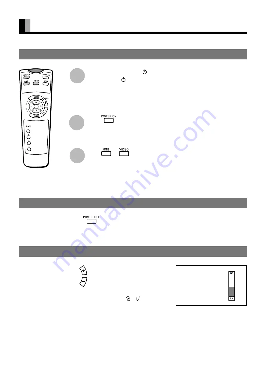
Press
to increase the volume.
Press
to reduce the volume.
Any value between 0 and 40 can be selected.
* “No Audio” appears if you press
or
after you have
selected “No Audio” for “Audio Input”. (See P. E-37.)
* Note that the volume level remains stored even when you
turn OFF the power.
ADJUSTING THE VOLUME
When the volume adjustment button is pressed


