MB95630H Series
MN702-00009-1v0-E
FUJITSU SEMICONDUCTOR LIMITED
223
CHAPTER 14 LIN-UART
14.6 Operations of LIN-UART and LIN-UART
Setting Procedure Example
14.6.1
Operations in Asynchronous Mode (Operating
Mode 0, 1)
When the LIN-UART is used in operating mode 0 (normal mode) or operating
mode 1 (multiprocessor mode), the transfer method is asynchronous transfer.
■
Operations in Asynchronous Mode
●
Transmit/receive data format
Transmit/receive data always begins with a start bit ("L" level), followed by a specified data
bits length, and ends with at least one stop bit ("H" level).
The bit transfer direction (LSB-first or MSB-first) is determined by the BDS bit in the LIN-
UART serial status register (SSR). When the parity bit is used, it is always placed between the
last data bit and the first stop bit.
In operating mode 0, the data length can be 7 bits or 8 bits. The use of the parity can be
selected. The stop bit length can also be selected from one and two.
In operating mode 1, the data length can be 7 bits or 8 bits. No parity is added while an
address/data bit is added. The stop bit length can be selected from one and two.
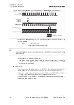
Below is the equation for the bit length of a transmit/receive frame.
Length = 1 + d + p + s
(d = Number of data bits [7 or 8], p = parity [0 or 1],
s = Number of stop bits [1 or 2])
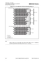
Figure 14.6-1 shows the transmit/receive data format in asynchronous mode (operating mode 0,
1).


