


135
CHAPTER 7 INTERRUPT
7.4.5
Hardware Interrupt Processing Time
From the generation of a hardware interrupt request to the execution of an interrupt
processing routine, the time for the instruction currently being executed to terminate
and the time required to handle an interrupt are necessary.
■
Hardware Interrupt Processing Time
From the generation of a hardware interrupt request to the acceptance of the interrupt and to the execution
of an interrupt processing routine, the time to wait for sampling for an interrupt request and the time
required to handle an interrupt (time to prepare for interrupt processing) are necessary. Figure 7.4-6 shows
the interrupt processing time.
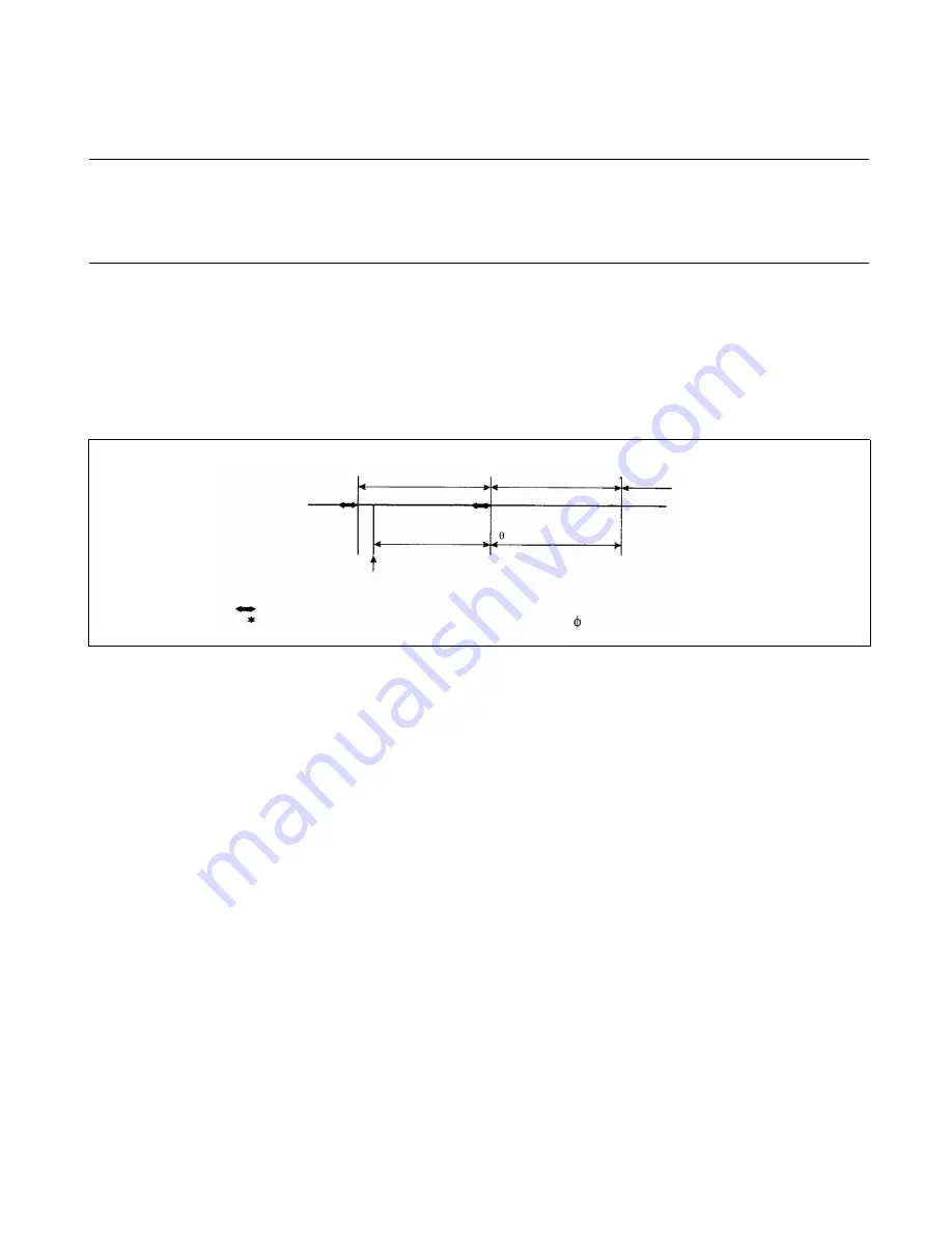
Figure 7.4-6 Interrupt Processing Time
●
Interrupt request sampling wait time
The interrupt request sampling wait time is the time from the generation of and interrupt request to the
termination of the instruction currently being executed.
Whether an interrupt request has been generated is determined by sampling the instruction for an interrupt
request in the final cycle of the instruction. Consequently, the CPU cannot identify an interrupt request
during execution of each instruction creating a delay.
The interrupt request sampling wait time is the maximum when an interrupt request is generated as soon as
the POPW RW0, ... RW7 instruction (45 machine cycles), which takes the longest to execute, starts.
CPU operation
Interrupt wait time
Interrupt request generation
Ordinary instruction
Interrupt request
Interrupt handling
execution
Interrupt processing
routine
sampling wait time
Interrupt handling time
( machine cycle) (
*
)
: The final instruction cycle samples the interrupt request here.
: One machine cycle corresponds to one machine clock ( ).
Summary of Contents for MB90460 Series
Page 1: ...The following document contains information on Cypress products ...
Page 3: ......
Page 5: ......
Page 9: ...iv ...
Page 41: ...22 CHAPTER 1 OVERVIEW ...
Page 45: ...26 CHAPTER 2 NOTES ON HANDLING DEVICES ...
Page 83: ...64 CHAPTER 3 CPU ...
Page 95: ...76 CHAPTER 4 RESET ...
Page 107: ...88 CHAPTER 5 CLOCK ...
Page 131: ...112 CHAPTER 6 LOW POWER CONSUMPTION MODE ...
Page 175: ...156 CHAPTER 7 INTERRUPT ...
Page 181: ...162 CHAPTER 8 MODE SETTING ...
Page 223: ...204 CHAPTER 9 I O PORT ...
Page 237: ...218 CHAPTER 10 TIME BASE TIMER ...
Page 247: ...228 CHAPTER 11 WATCHDOG TIMER ...
Page 275: ...256 CHAPTER 12 16 BIT RELOAD TIMER ...
Page 373: ...354 CHAPTER 14 MULTI FUNCTIONAL TIMER ...
Page 485: ...466 CHAPTER 16 PWC Timer ...
Page 531: ...512 CHAPTER 17 UART ...
Page 559: ...540 CHAPTER 19 DELAYED INTERRUPT GENERATOR MODULE ...
Page 589: ...570 CHAPTER 20 8 10 BIT A D CONVERTER ...
Page 601: ...582 CHAPTER 21 ROM CORRECTION FUNCTION ...
Page 633: ...614 CHAPTER 23 512K 1024K BIT FLASH MEMORY ...
Page 645: ...626 CHAPTER 24 EXAMPLE OF F2 MC 16LX MB90F462 F462A F463A CONNECTION FOR SERIAL WRITING ...
Page 715: ...696 APPENDIX ...
Page 716: ...697 INDEX INDEX The index follows on the next page This is listed in alphabetic order ...
Page 739: ......