


CHAPTER 3
Small Configuration
Installing Cables
3-109
FLASHWAVE 7500 Release 6.1
Equipment Installation
Fujitsu and Fujitsu Customer Use Only
FNC-7500-0061-200
Issue 1, May 2009
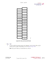
3.19.3
Optical/Tributary Shelf Backplane
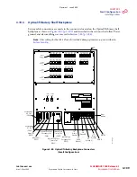
System cable connections are made to the connectors located on the Optical/Tributary shelf
backplane as shown in
and described in the sections that follow. Power,
ground, and alarm cabling was covered in
Note:
Fiber cabling for the LAS2 (if used) is installed during system turn-up as described in
.
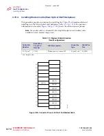
Figure 3-83: Optical/Tributary Backplane Connectors
(Small Configuration)
Power
Interface
Housekeeping
#2 Port
(CN40)
Alarm Port
(CN42)
External Clock
Primary Port
(CN47)
External Clock
Secondary Port
(CN46)
Modem Port
(CN43)
Internal Shelf Clock
Secondary Port
(CN44)
Internal Shelf Clock
Primary Port
(CN45)
Housekeeping
#1 Port
(CN41)
GB
(Ground B)
GA
(Ground A)
FG
(Frame
Ground)
MAIN B
MAIN A
FG
(Frame
Ground)
COM2
CN39
COM1
CN38
CAUTION
ATTENTION
SG
(Signal
Ground)
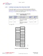
LAN1
CN1
LAN2
CN2
LAN3
CN3
LAN4
CN4
LAN5
CN5
LAN6
CN6
LAN7
CN7
LAN8
CN8
LAN9
CN9
LAN10
CN10
LAN11
CN11
OSS
CN12
PORT1
CN24
PORT2
CN25
PORT3
CN26
PORT4
CN27
PORT5
CN28
PORT6
CN29
PORT7
CN30
PORT1
CN31
PORT2
CN32
PORT3
CN33
PORT4
CN34
PORT5
CN35
PORT6
CN36
PORT7
CN37
LAN1
CN13
LAN2
CN14
LAN3
CN15
LAN4
CN16
LAN5
CN17
LAN6
CN18
LAN7
CN19
LAN8
CN20
LAN9
CN21
LAN10
CN22
LAN11
CN23
INT SHF
(MPMA-1)
Ports
INT SHF
(MPMA-2)
Ports
RICC
(MCMA-1)
Ports
RICC
(MCMA-2)
Ports
FUJITSU LIMITED
m1
71
4ng_2
Revision 1, June 2009
Summary of Contents for FLASHWAVE 7500
Page 8: ...Revision 1 June 2009 ...
Page 10: ...Revision 1 June 2009 ...
Page 16: ...Revision 1 June 2009 ...
Page 362: ...Revision 1 June 2009 ...
Page 386: ...Revision 1 June 2009 ...


