background image

9

5. Software Setup

In the software setup procedure, you install and operate the software applications.
This chapter includes the installing and operating procedure for each software in order. Check the 
contents and complete the software setup.

Installation of software

- Installing S

OFTUNE

- Installing USB driver
- Installing sample program

Operation of S

OFTUNE

- Starting S

OFTUNE

 Workbench

- Starting Debugging
- Initializing MCU
- Running the program
- Aborting the program
- Ending Debugging
- Exiting S

OFTUNE

 Workbench

5.1 Installation of software

This section describes how to install S

OFTUNE

 and the USB driver in your host machine, as well as 

how to install the sample program.

Installing 

S

OFTUNE

Follow the instruction described in "F

2

MC-8L/8FX Family 8-bit Microcontroller S

OFTUNE

 Work-

bench Installation Guide" to install S

OFTUNE

 in your host machine.

Installing USB driver

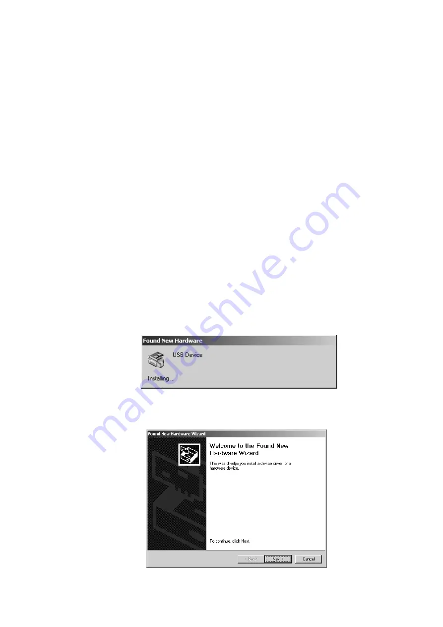
Plug a USB cable connected to BGM Adapter into your host machine. After you connect the host 
machine and the BGM Adapter, the [Found New Hardware Wizard] window appears. Follow the in-
struction below to install the USB driver.

In a few seconds after the above dialog is displayed, the [Welcome to the Found New Hardware Wiz-
ard] screen appears. Click [Next] to install the device driver.

Summary of Contents for F2MC Series

Page 1: ...FUJITSU SEMICONDUCTOR SUPPORT SYSTEM SS01 26008 1E F2 MC Series F2 MC 8FX STARTER KIT ver 5V MB2146 401 03 SETUP GUIDE ...

Page 2: ...troller Handling and use Handling and use of this product and notes regarding its safe use are described in the manuals for products bundled with the Starter Kit Follow the instructions in the manuals to use this product Keep this manual at hand so that you can refer to it anytime during use of this product Caution of the products described in this document The following precautions apply to the p...

Page 3: ...al of each product for the range of the specification Operating it outside the range of any general specification may cause a fault Damage To prevent electrostatic breakdown do not let your finger or an object touch any metal part of the connector Before handling the product touch a metal object such as a door knob to discharge static electricity from your body Damage When turning the power on or ...

Page 4: ...in The products described in this document are designed developed and manufactured as contemplated for general use including without limitation ordinary industrial use general office use personal use and household use but are not designed developed and manufactured as contemplated 1 for use accompanying fatal risks or dangers that unless extremely high safety is secured could have a serious effect...

Page 5: ...g the Delivered Product 1 2 Handling Precautions 1 3 Feature 2 4 Hardware Setup 2 4 1 Configuration of each product 3 4 2 Connection of each product 5 5 Software Setup 9 5 1 Installation of software 9 5 2 Operation of SOFTUNE 13 ...

Page 6: ...ur host machine The duration of this version is limited to 45 days MB2146 401 01 is used as a starter kit for F2 MC 8FX MB95FV100 103 ver 5V by combining with the bundled products For details about this product consult our Sales or Support representatives 2 Handling Precautions The Starter Kit can be used in connection with its bundled products To ensure correct use of this product in a proper env...

Page 7: ...U of operation Compact development environment a light and small BGM Adapter Since a monitor program is performed in exclusive memory space it does not consume user memory space Continuation execution step execution a command break a data break sequential break cor respondence Command trace is possible a maximum of 16 branches It connects with a host machine by the USB interface 4 Hardware Setup I...

Page 8: ...or 64 pin package set the value to 2 For 48 pin package set the value to 3 For none of the above check on the settings in the MCU Board manual LVD selector switch Set the value to OFF Miscellaneous switches Set C to ON Set CLK to OFF if you use subclock or ON if you don t Set the other switches to OFF to the side of numeral letters Clock input selector switch Set all to OFF to the side of numeral ...

Page 9: ...rion 5V 3 3V Power supply selector jumper plug Set the value to the side of 5V Analog power supply jumper plug Insert jumper plug for all the switches MOD selector jumper plug Insert jumper plug Figure 2 Evaluation Board Configuration SW1 JP6 JP5 JP3 JP4 1 2 119 120 1 2 119 120 CN3 JP1 JP2 CN4 PJ1 SW2 JP7 CN2 CN1 JP8 3 3V 5V 2 1 3 ...

Page 10: ...cting MCU Board and Evaluation Board Connect the MCU Board and the Evaluation Board referring to Figure 3 Connection of MCU Board and Evaluation Board Each board has an index to avoid the reverse mounting Look at the index position to connect the boards Figure 3 Connection of MCU Board and Evaluation Board SW1 JP6 JP5 1 2 119 120 1 2 119 120 CN3 JP1 JP2 CN4 PJ1 SW2 JP7 CN2 CN1 JP3 JP4 3 3V 5V Eval...

Page 11: ...rk on both sides Plug a USB cable into the BGM Adapter the cable is bundled with the BGM Adapter Make sure that POWER SW on the Evaluation Board is set to OFF to the side of before plug ging the cable Figure 4 Connection of BGM Adapter SW1 JP6 JP5 CN3 JP1 JP2 CN4 PJ1 SW2 JP7 MB2146 09 JP3 JP4 3 3V 5V Plug into BGM Adapter USB cable Bundled with BGM Adapter BGM Adapter MCU Board Evaluation Board Po...

Page 12: ...tal oscillator mounting socket for main clock Mount a crystal oscillator used as main clock Crystal oscillator mounting socket for subclock Mount a crystal oscillator used as subclock If you disable the subclock set the CLK switch to ON Figure 5 Connection of oscillators BGM ADAPTER SUB CLOCK C B A 1 2 CLK CLK S V APB8 C X0 X1 X0A X1A 7 6 5 4 3 2 10F E D C B A 9 8 PRODUCT SELECT LVD4 LVD3 LVD2 LVD...

Page 13: ...n of AC Adapt er The AC Adapter bundled with the Evaluation Board is plugged into the PJ1 on Evaluation Board and the AC 100V Power Supply Figure 6 Connection of AC Adapter SW1 JP6 JP5 CN3 JP1 JP2 CN4 PJ1 SW2 JP7 MB2146 09 JP3 JP4 3 3V 5V BGM Adapter Plug into Evaluation Board AC Adapter Evaluation Board ...

Page 14: ...n of software This section describes how to install SOFTUNE and the USB driver in your host machine as well as how to install the sample program Installing SOFTUNE Follow the instruction described in F2 MC 8L 8FX Family 8 bit Microcontroller SOFTUNE Work bench Installation Guide to install SOFTUNE in your host machine Installing USB driver Plug a USB cable connected to BGM Adapter into your host m...

Page 15: ...ck Next to search for a suitable driver for your device The Locate Driver Files screen appears Check Specify a location and then click Next to specify the location for the driver A file location dialog appears Select SiUSBdB INF in the Drivers folder under a directory where SOFTUNE is installed and click Open to specify the driver ...

Page 16: ...rectory where SOFTUNE is installed is selected and click OK The Driver Files Search Results screen appears Click Next to start installing the driver The Completing the Found New Hardware Wizard screen appears Now that the USB driver installation has completed click Finish to exit the Wizard ...

Page 17: ...properties and deselect the Read Only checkbox and click OK In the Confirm Attribute Change dialog check Apply Changes to this folder sub folders and files and click OK to confirm the attribute change Note This software application uses the reload timer so it cannot be used in 48 pin package or less which does not implement the reload timer When using this software set 64 pin package or more in th...

Page 18: ... the sample program Starting SOFTUNE Workbench Start SOFTUNE and configure the SOFTUNE development environment From the File menu click Open Workspace In a file location dialog select the sample fsg 8fx_sample folder under a directory where SOFTUNE is installed and specify fsg_sample wsp then click Open ...

Page 19: ...14 Select and right click emu_dbg sup under the Debug folder then click Change Settings to start the setup wizard ...

Page 20: ...15 The setup wizard is started Click Next In Debug Type specify Emulator Debugger and click Next In ICE Type specify MB2146 09 and click Next ...

Page 21: ...16 In Device Name specify USB and click Next In Output Frequency set the frequency of oscillator connected to MCU Board and click Next The Batch file setting is not required Click Next ...

Page 22: ...hen starting debug and specify fsg_sample prc in After under Specifica tion batch file before after load then click Next Check Select All and click Next Click Finish to complete the setup of SOFTUNE development environment ...

Page 23: ...n Board on Push POWER SW on the Board to ON to the side of to turn it on See Connecting BGM Adapter for information about POWER SW After the Evaluation Board is turned on click Start debug from the Debug menu to start debug ging When you start debugging the sample program is automatically loaded ...

Page 24: ...19 Initializing MCU Initialize MCU To do so click the Reset button on the task bar Reset button ...

Page 25: ...he program by clicking the execution related buttons on the task bar You can also set a breakpoint by clicking the mark in the Source window Source window Execution related buttons Go Step In Step Over Step Out Run Until Cursor Breakpoint ...

Page 26: ...21 Aborting the program After you have run the program you can stop it by clicking the Abort button on the task bar Abort button ...

Page 27: ...bug from the Debug menu Turning Evaluation Board off After you have finished debugging turn the Evaluation Board off for safety Push POWER SW on the Board to OFF to the side of to turn it off See Connecting BGM Adapter for informa tion about POWER SW ...

Page 28: ...23 Exiting SOFTUNE Workbench To exit SOFTUNE Workbench click Exit from the File menu ...

Page 29: ...1E FUJITSU SEMICONDUCTOR SUPPORT SYSTEM F2 MC Series F2 MC 8FX STARTER KIT ver 5V MB2146 401 03 SETUP GUIDE March 2005 the first edition Published FUJITSU LIMITED Electronic Devices Edited Business Promotion Dept ...

Page 30: ......

Reviews: