background image

Chapter 4  Connecting Cables
  4.5  Power Cord Connection

FUJITSU Storage ETERNUS DX60 S2 Disk storage system User’s Guide -Installation-

75

Copyright 2014 FUJITSU LIMITED

P3AM-5502-05ENZ0

2

Connect the power distribution unit outlets and power supply unit inlets with the 
power cords (AC output cables, 3m) provided with the power distribution unit.

The procedures to connect the power supply unit is same as the 

Step 1

 in 

"4.5.1 When no 

Power Distribution Units are Installed" (page 72)

.

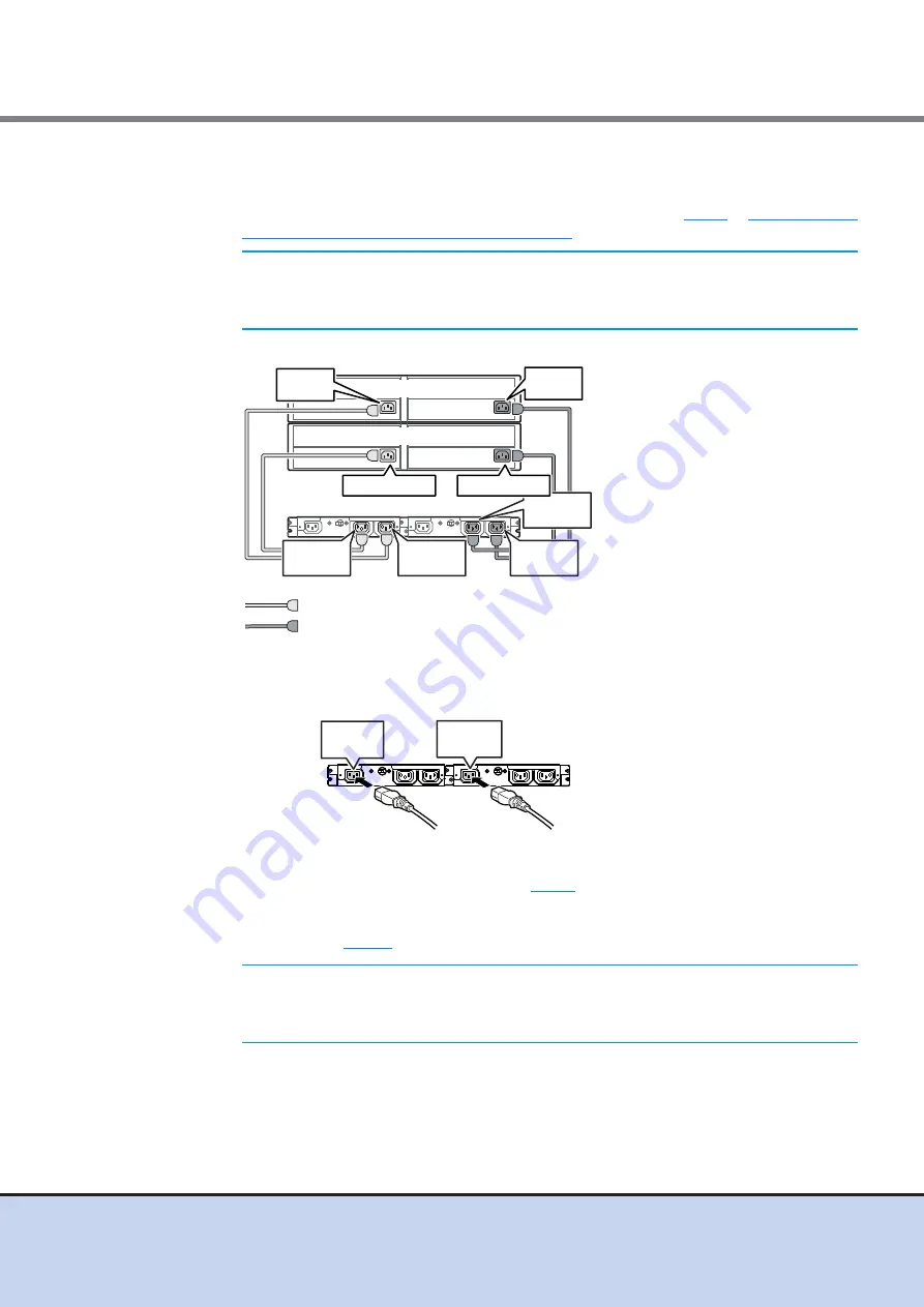
The following figure shows an example of AC output cable connection:

3

Connect the power cords (AC input cables) supplied with the power distribution 
unit to the inlet of the power distribution unit.

4

Use the power cord clamps to prevent the power plugs from coming unplugged.

Attach the power cord clamps removed in 

Step 1

.

5

Connect the plug at the other end of each of the power cords (AC input cables) 
connected in 

Step 3

 to the outlet.

IMPORTANT

Each enclosure has two power supply units (PSU#0 and PSU#1). 
The power cords must be connected to the inlets of both power 
supply units.

IMPORTANT

Power supply failure can be prevented by connecting the power 
cords (AC input cables) on the power distribution unit A side and the 
power distribution unit B side to different power sources.

Drive Enclosure 

Controller Enclosure

Outlet

OUTPUT#1-1

Outlet

OUTPUT#0-1

Outlet

OUTPUT#0-2

Outlet

OUTPUT#1-2

PSU#1 Inlet

PSU#0 Inlet

PSU#1 Inlet

PSU#0 Inlet

Power distribution unit

: Connect between the OUTPUT#1-n of the power distribution unit
  and the PSU#1 inlets of the ETERNUS DX Disk storage system

: Connect between the OUTPUT#0-n of the power distribution unit
  and the PSU#0 inlets of the ETERNUS DX Disk storage system

Power
distribution unit

Inlet

INPUT #0

Inlet

INPUT #1

Summary of Contents for ETERNUS DX60 S2

Page 1: ......

Page 2: ...This page is intentionally left blank ...

Page 3: ...or use of the FUJITSU Storage ETERNUS DX60 S2 Disk storage sys tem in regions other than Japan Please carefully review the information outlined in this manual Fifth Edition January 2014 Microsoft Windows Windows Server and Internet Explorer are either registered trademarks or trademarks of Microsoft Corporation in the United States and other countries Mozilla Firefox and the Mozilla and Firefox lo...

Page 4: ...ge ETERNUS DX60 S2 Disk storage system Chapter 2 Components This chapter describes the components of the FUJITSU Storage ETERNUS DX60 S2 Disk storage system Chapter 3 Rack Installation This chapter explains how to install the FUJITSU Storage ETERNUS DX60 S2 Disk storage system in a rack Chapter 4 Connecting Cables This chapter explains how to connect cables to the FUJITSU Storage ETERNUS DX60 S2 D...

Page 5: ...mbol indicates the possibility of minor or moderate personal injury as well as damage to the FUJITSU Storage ETERNUS DX60 S2 Disk storage system and or to other users and their property if the FUJITSU Storage ETERNUS DX60 S2 Disk storage system is not used properly IMPORTANT This symbol indicates IMPORTANT information for the user to note when using the FUJITSU Storage ETERNUS DX60 S2 Disk storage...

Page 6: ...ual The following is an expression used throughout this manual Abbreviations Used in This Manual ETERNUS DX Disk storage system or ETERNUS DX60 S2 refers to the FUJITSU Storage ETERNUS DX60 S2 Disk storage system Host Bus Adapter HBA refers to the interface module that is normally used by the server to connect to ETERNUS DX Disk storage systems An FC card LAN card Network Interface Card NIC or SAS...

Page 7: ...vice ID label are found in various places of the ETERNUS DX Disk storage system as shown in the example below Do not remove these labels ETERNUS DX60 S2 controller enclosure Manufacturer s label The label with the model and serial is located here Rear of the controller enclosure Front of the controller enclosure Device ID label The label with the model and serial is located here Front of the contr...

Page 8: ...s Labels FUJITSU Storage ETERNUS DX60 S2 Disk storage system User s Guide Installation 8 Copyright 2014 FUJITSU LIMITED P3AM 5502 05ENZ0 Drive enclosure Power distribution units for regions other than EMEA I Power distribution unit 1U ...

Page 9: ...rning Labels and Manufacturer s Labels FUJITSU Storage ETERNUS DX60 S2 Disk storage system User s Guide Installation 9 Copyright 2014 FUJITSU LIMITED P3AM 5502 05ENZ0 Power distribution unit AC200 240V 2U ...

Page 10: ... 4 Components Rear 41 2 3 Power Distribution Units For Regions other than EMEA I 43 2 3 1 Power Distribution Units 1U 43 2 3 2 Power Distribution Units 2U 44 Chapter 3 Rack Installation 45 3 1 Installing Power Distribution Unit For Regions other than EMEA I 46 3 1 1 Installing Power Distribution Unit 1U 46 3 1 2 Installing Power Distribution Unit 2U 48 3 2 Installing Controller Enclosure 50 3 3 In...

Page 11: ... 1 ETERNUS DX Disk Storage System and PC Terminal Connection 80 5 1 2 Powering On 81 5 1 3 Start up ETERNUS Web GUI 83 5 1 4 Initial Setup 84 5 1 5 Configuration Wizard 92 5 1 6 Assign Hot Spare 104 5 2 ETERNUS DX Disk Storage System Monitoring Setup 107 5 2 1 Setup Event Notification 107 5 2 2 Setup E Mail Notification 110 5 2 3 SNMP Trap Setup 111 5 2 4 Remote Support Setup For Regions other tha...

Page 12: ...sure single controller type 28 Figure 2 5 Rear view of a controller enclosure dual controller type 28 Figure 2 6 Operation panel 2 5 type controller enclosure 29 Figure 2 7 Operation panel 3 5 type controller enclosure 29 Figure 2 8 2 5 type disk 31 Figure 2 9 Disk slot numbers 2 5 type controller enclosure 31 Figure 2 10 3 5 type disk 32 Figure 2 11 Disk slot numbers 3 5 type controller enclosure...

Page 13: ...atus and meanings of each LED 3 5 disks 32 Table 2 4 Status and meanings of each LED FC model controller 34 Table 2 5 Status and meanings of each LED iSCSI model controller 35 Table 2 6 Status and meanings of each LED SAS model controller 36 Table 2 7 Status and meanings of each LED power supply unit 38 Table 2 8 Status and meanings of each LED in front of drive enclosure 40 Table 2 9 Status and m...

Page 14: ...terfaces can be used for the host interface The connection destination may be the server or the switch depending on which connection configuration is used For the possible combinations of servers Host Bus Adapters HBAs and switches refer to Server Support Matrix by accessing the URL that is described in READ ME on the Documentation CD provided with the ETERNUS DX Disk storage system The host inter...

Page 15: ...Controller Master CM Slave CM For a dual controller type the controller CM that is given the authority to manage the LAN is called the Master CM and the other CM is called the Slave CM When an error occurs in the Master CM or LAN the Master CM is switched automatically IP addresses of the LAN ports are not assigned to each CM These IP addresses are assigned to the role of master or slave If the Ma...

Page 16: ...o connect an ETERNUS DX Disk storage system to the LAN Each CM has an LED that lights up green to identify when it is the Master CM Setting the IP address of the Slave CM ensures that ETERNUS Web GUI or ETERNUS CLI can be used from the Slave CM if an error occurs on the LAN path for the Master CM The Master CM and the Slave CM perform different functions The Slave CM can only switch the Master CM ...

Page 17: ... is used for maintenance operations performed by a maintenance engineer Network devices such as LAN switches are required for operation management Two enhanced Cat 5 twisted pair type LAN cables are required to connect the ETERNUS DX Disk storage system to the LAN for operation management Figure 1 3 LAN connection example IP x x x a LAN switch SNMP manager NTP server Mail server LAN for operation ...

Page 18: ...used for maintenance operations performed by a maintenance engineer Network devices such as LAN switches are required for operation management Two enhanced Cat 5 twisted pair type LAN cables are required to connect the ETERNUS DX Disk storage system to the LAN for operation management Figure 1 4 LAN connection example when the IP address of the Slave CM is set IP x x x a IP x x x b IP addresses fo...

Page 19: ... Disk storage system one IP address for the MNT port is required An IP address is required for a PC terminal that is used for maintenance operations performed by a maintenance engineer Network devices such as LAN switches are required for operation management Two enhanced Cat 5 twisted pair type LAN cables are required to connect the ETERNUS DX Disk storage system to the LAN for operation manageme...

Page 20: ...maintenance engineer Network devices such as LAN switches are required for operation management Four enhanced Cat 5 twisted pair type LAN cables are required two for connection to the remote support center and two for connection to the LAN for operation management Figure 1 6 Connection example with a dedicated remote support port IP x x x a Operation is performed with separate LANs for the MNT por...

Page 21: ... Network devices such as LAN switches are required for operation management Two enhanced Cat 5 twisted pair type LAN cables are required to connect the ETERNUS DX Disk storage system to the LAN for operation management Figure 1 7 Connection example when the IP address of the Slave CM is set and a dedicated remote support port is not used IP x x x a IP x x x b RMT ports are not used IP addresses fo...

Page 22: ...Cat 5 twisted pair type LAN cables are required two for connection to the remote support center and two for connection to the LAN for operation management Figure 1 8 Connection example when the IP address of the Slave CM is set and a dedicated remote support port is used IP x x x a IP x x x b Operation is performed with separate LANs for the MNT port and the RMT port The IP addresses of both the M...

Page 23: ...lowing Storage Foundation Software ETERNUS SF refer to the manual of each Storage Foundation Software ETERNUS SF ETERNUS SF Storage Cruiser ETERNUS SF AdvancedCopy Manager ETERNUS SF Express Usage Protocol tcp udp Port number Direction Master CM Slave CM Remarks MNT RMT MNT RMT ETERNUS Web GUI http https tcp 80 443 from Yes No 1 1 Accessed from a Web browser ETERNUS CLI telnet ssh tcp 23 22 from Y...

Page 24: ...ary for the network configuration Disable the STP function of the LAN switch port only for the ETERNUS DX Disk storage system connection or perform the Port Fast setting 1 2 Setup Preparation Perform the following preparation to set up the ETERNUS DX Disk storage system Completing and attaching the Network Settings label Preparation and settings for the PC terminal Completing and attaching the Net...

Page 25: ...et up the PC terminal before the initial settings Preparing the PC terminal Prepare the PC terminal that contains the following environment Web browser Usable Web browsers are as follows Using Web browsers other than the following is possible but proper operation is not guaranteed Microsoft Internet Explorer 6 0 7 0 8 0 9 0 10 0 desktop version Mozilla Firefox 3 0 x 3 5 x 3 6 x ESR 10 0 x ESR 17 0...

Page 26: ...5502 05ENZ0 Setting up the PC terminal Set up the PC terminal with the following procedure Procedure 1 Set the IP address and subnet mask of the PC terminal Set the following values IP address 192 168 1 2 Subnet Mask 255 255 255 0 2 Check the settings of the Web browser Proxy server and Cache Disable Java Script style sheets and cookies Enable End of procedure ...

Page 27: ...talled in the front of the controller enclosure Controllers and power supply units are installed in the rear 2 1 1 Front View 2 5 type Figure 2 1 Front view of a 2 5 type controller enclosure 3 5 type With front cover Figure 2 2 Front view of a 3 5 type controller enclosure with front cover Without front cover Figure 2 3 Front view of a 3 5 type controller enclosure without front cover Operation p...

Page 28: ...AM 5502 05ENZ0 2 1 2 Rear View Single controller type Figure 2 4 Rear view of a controller enclosure single controller type Dual controller type Figure 2 5 Rear view of a controller enclosure dual controller type Cover Power Supply Unit PSU 0 Power Supply Unit PSU 1 Controller CM 0 Controller CM 0 Power Supply Unit PSU 0 Controller CM 1 Power Supply Unit PSU 1 ...

Page 29: ...EDs a power switch an AUTO POWER switch a MODE SELECT switch and an IP RESET switch 2 5 type Figure 2 6 Operation panel 2 5 type controller enclosure 3 5 type Figure 2 7 Operation panel 3 5 type controller enclosure With a flange cover Without a flange cover AUTO POWER switch IP RESET switch MODE SELECT switch Power switch CACHE LED POWER LED READY LED FAULT LED IDENTIFY LED With a front cover Wit...

Page 30: ...rom the current controller to the other controller Click twice in succession within a two second interval to revert the LAN port settings of the ETERNUS DX Disk storage system to their factory settings LEDs The states of LEDs are listed below Table 2 1 Status and meanings of each LED operation panel controller enclosure LED name LED status ETERNUS DX Disk storage system status POWER green DC power...

Page 31: ...listed below Table 2 2 Status and meanings of each LED 2 5 disks WARNING Do Not System disks are installed in Slot 0 and Slot 1 Never remove system disks Doing so will render the ETERNUS DX Disk storage system unusable LED name LED status Disk status DISK READY green The disk is operating normally blinks green DISK FAULT orange The disk is in error status DISK FAULT LED DISK READY LED Slot 8 Slot ...

Page 32: ...enclosure Part explanation LEDs The states of LEDs are listed below Table 2 3 Status and meanings of each LED 3 5 disks WARNING Do Not System disks are installed in Slot 0 and Slot 1 Never remove system disks Doing so will render the ETERNUS DX Disk storage system unusable LED name LED status Disk status DISK READY FAULT green The disk is operating normally blinks green orange The disk is in error...

Page 33: ... DX Disk storage system FC model Figure 2 12 Controller FC model Part explanation LAN RMT port LAN MNT port These are the RJ 45 connectors to connect LAN cables LAN RMT port is not used in the EMEA I region A single controller has one LAN RMT port and one LAN MNT port FC port 0 left 1 right These are the Dual LC connectors to connect FC cables PWC port This port is used for power synchronization D...

Page 34: ...een established FC LINKUP FAULT green The link between the FC port host interface port and the destination has been established orange The FC port host interface port is in error status UNIT READY FAULT green The controller is in normal status orange The controller is performing the initial setup after the power is turned on The controller is in error status MASTER green The controller is set as a...

Page 35: ... SCU STATUS green The SCU is in normal status blinks green SCU is charging IDENTIFY blinks blue As ordered via ETERNUS Web GUI the installation location of the controller enclosure is identified off DI OUT LINKUP green The link between the DI OUT port and the destination has been established UNIT READY FAULT green The controller is in normal status orange The controller is performing the initial s...

Page 36: ...r synchronization DI OUT port This port is used to connect a controller enclosure to a drive enclosure with a miniSAS cable LEDs The states of LEDs are listed below Table 2 6 Status and meanings of each LED SAS model controller LED name LED status Controller status SCU STATUS green The SCU is in normal status blinks green SCU is charging IDENTIFY blinks blue As ordered via ETERNUS Web GUI the inst...

Page 37: ... DC power and supplies power to each component Each power supply unit contains a fan Figure 2 15 Power supply unit Part explanation Inlet This inlet is used to connect a power cord LEDs The states of LEDs are listed below SAS HOST LINKUP FAULT green The link between the SAS port host interface port and the destination has been established orange The SAS port host interface port is in error status ...

Page 38: ...ew With front cover Figure 2 16 Front view of a drive enclosure with front cover Without front cover Figure 2 17 Front view of a drive enclosure without front cover LED name LED status Power supply unit status STATUS green AC power is supplied to the power supply unit and the ETERNUS DX Disk storage system DC power is turned on blinks green AC power is supplied to the power supply unit but the ETE...

Page 39: ...nents Front This section describes the operation panel and the disks in the front of the drive enclosure Operation panel An operation panel has LEDs an AUTO POWER switch a MODE SELECT switch and an IP RESET switch Figure 2 20 LEDs on the front side of the drive enclosure Power Supply Unit PSU 0 Power Supply Unit PSU 1 Expander EXP 0 Cover Power Supply Unit PSU 0 Power Supply Unit PSU 1 Expander EX...

Page 40: ...d meanings of each LED in front of drive enclosure Disk Figure 2 21 3 5 disk Figure 2 22 shows the slot number of each disk Figure 2 22 Disk slot numbers drive enclosure Part explanation LEDs The states of LEDs are listed below LED name LED status Drive enclosure status POWER green DC power is supplied to the drive enclosure READY green The ETERNUS DX Disk storage system is available for use FAULT...

Page 41: ...supply units in the rear of the drive enclosure Expander The expander is a component that controls how the controller and the disks interact Figure 2 23 Expander Part explanation DI IN port These ports are connectors for miniSAS cables LEDs The states of LEDs are listed below LED name LED status Disk status DISK READY FAULT green The disk is operating normally blinks green orange The disk is in er...

Page 42: ... status IDENTIFY blinks blue As ordered via ETERNUS Web GUI the installation location of the drive enclosure is identified off DI IN LINKUP LED green The link between the DI IN port and the destination has been established orange The DI IN port is in error status UNIT READY FAULT green The expander is in normal status orange The controller is performing the initial setup after the power is turned ...

Page 43: ... Distribution Units 1U The 1U power distribution unit has four outlets and two inlets Power Distribution Units 1U Figure 2 25 Power distribution unit 1U Part explanation Main line switch This turns on and off the power distribution unit Inlet INPUT This is a socket IEC60320 C13 for incoming power supply This socket is used to connect a power cord AC input cable Outlet OUTPUT This is a socket IEC60...

Page 44: ...s Figure 2 26 Power distribution unit 2U Max 6 enclosures connection Part explanation Main line switch This turns on and off the power distribution unit Outlet OUTPUT This is a socket IEC60320 C13 for outgoing power supply This socket is used to connect a power cord AC output cable Power Distribution Units 2U Max 8 enclosures connection There are 16 outlets Figure 2 27 Power distribution unit 2U M...

Page 45: ...isk storage system contains delicate components and should be handled gently Do not drop or knock the ETERNUS DX Disk storage system against the rack when installing it Also do not knock the other devices installed in the rack The center of gravity must be taken into consideration to prevent a rack from toppling over Enclosures should generally be installed from bottom to top to lower the center o...

Page 46: ...nstall the power distribution unit in a rack 3 1 1 Installing Power Distribution Unit 1U This section describes how to install the 1U power distribution unit in a rack Procedure 1 Remove the two brackets temporarily attached to the power distribution unit Remove the two M3 screws from the front of the power distribution unit to free the brackets CAUTION Do Not Do not connect any devices other than...

Page 47: ...on unit base line The M6 screws should be inserted in the 1st and 3rd holes above the base line 3 Install the power distribution unit in the rack Fasten the power distribution unit to the bracket with the two M3 screws removed in Step 1 Rear rack pillars Bracket B Screw holders M6 screws Screw holders Bracket A Holder Holder M6 screws Power distribution unit 1U Rear rack pillars Brackets Base line...

Page 48: ...es execution in a rack Procedure 1 Attach the M5 cage nuts to the rear rack pillar Attachment positions On either side insert eight M5 cage nuts in the 1st 3rd 4th and 6th holes above the power distribution unit base line Rear rack pillars Front rack pillars Blank panel Power distribution unit This section explains the connection procedure for power distribution units 2U Max 6 enclosures connectio...

Page 49: ...e nut tabs into the desired hole from the inside 2 Install the power distribution unit in the rack Fasten it to the prepared holes in the pillars with eight M5 screws 3 Attach the blank panel to the rack front The blank panel should be attached at the same height as the power distribution unit End of procedure Side view M5 cage nut Rack pillar square Rear rack pillars M5 screws M5 screws Power dis...

Page 50: ...e 1 Attach the rack rails to the rack For the EMEA I region 1 Attach the 2U Bracket to the left rear rack pillar The M5 centering screws should be inserted in the 1st and 6th holes above the base line of the controller enclosure CAUTION Do Not Do not uninstall the disks that are installed by default or move them to any other slot Contact your sales representative or maintenance engineer if disks t...

Page 51: ... to the front pillar in the same way as the left slide rail 5 Push the M5 cage nuts into the 2nd holes of the front rack pillars above the base line of the controller enclosure The M5 centering screw and M5 pan head screw positions for the slide rails and 2U Bracket are determined relatively to the base line of the controller enclosure Tighten the screws referring to the following figure M5 Center...

Page 52: ... they can be completely tightened 2 Attach the rack rails to the rack If the rack pillars have square approx 9mm holes screw holders will need to be used when attaching the rack rails brackets Make sure to attach the rack rails and rack pillars so that they fit exactly together without any space between them Front rack pillars Left Right Bracket L for left side L is stamped on the inner side of th...

Page 53: ...e slightly unscrewed in Step 1 2 Install the controller enclosure in the rack 3 Fix the controller enclosure in the rack 2 5 type controller enclosure 1 Use the thumb screw to fasten the front right of the controller enclosure to the rack CAUTION Do When installing or removing the controller enclosure to or from the rack make sure to have the right and left sides and the bottom of the controller e...

Page 54: ...NZ0 2 Attach the flange cover to the front left of the controller enclosure Slide the tab inside the top of the flange cover over the top left corner of the controller enclosure 3 Use the thumb screw of the flange cover to fasten the front left of the controller enclosure to the rack IMPORTANT When fitting the flange cover be careful not to touch the power switch Flange cover Thumb screw ...

Page 55: ...e controller enclosure Use the two thumb screws at the front of the controller enclosure to fasten it to the rack 4 For 3 5 type controller enclosures attach the front cover 4 1 Fit the front cover in the left end slot of the controller enclosure to attach IMPORTANT Be careful so that the part of the front cover to be fit in the slot does not touch the power switch Rear rack pillars Thumb screw Sl...

Page 56: ...section describes how to install a drive enclosure in a rack CAUTION Do When attaching the right side of the front cover support its left side with your left hand to prevent it from coming loose and falling Tab CAUTION Do Not Do not uninstall the disks that are installed by default or move them to any other slot Contact your sales representative or maintenance engineer if disks that are installed ...

Page 57: ...e rack For the EMEA I region 1 Attach the 2U Bracket to the left rear rack pillar The M5 centering screws should be inserted in the 1st and 6th holes above the base line of the drive enclosure 2 Insert the pins of the left slide rail in the 1st and 3rd holes from the bottom of the 2U Bracket 3 Secure the left slide rail to the front pillar using the M5 centering screw and M5 pan head screws M5 Cen...

Page 58: ...r regions other than EMEA I 1 Adjust the sizes of the rack rail for left side and the rack rail for right side to fit the rack Loosen the M4 screws to adjust the length of the rack rails to match the distance between the front and rear rack pillars Leave the M4 screws slightly unscrewed as the rack rails must be attached to the rack before they can be completely tightened M5 Centering screw 10mm M...

Page 59: ...k If the rack pillars have square approx 9mm holes screw holders will need to be used when attaching the rack rails brackets Make sure to attach the rack rails and rack pillars so that they fit exactly together without any space between them CAUTION Do When installing or removing the drive enclosure to or from the rack make sure to have the right and left sides and the bottom of the drive enclosur...

Page 60: ...2 05ENZ0 3 Fix the drive enclosure in the rack Use the two thumb screws at the front of the drive enclosure to fasten it in the rack 4 Attach the front cover 4 1 Fit the front cover in the left end slot of the drive enclosure to attach IMPORTANT Be careful so that the part of the front cover to be fit in the slot does not touch the power switch Rear rack pillars Thumb screw Slot ...

Page 61: ...e Installation 61 Copyright 2014 FUJITSU LIMITED P3AM 5502 05ENZ0 4 2 Holding the tab on the front cover attach the right side of the cover to the enclosure End of procedure CAUTION Do When attaching the right side of the front cover support its left side with your left hand to prevent it from coming loose and falling Tab ...

Page 62: ...ained separately The following explains how to connect the LAN cable CAUTION Do When performing the installation make sure to wear a wrist strap or touch a metal part to discharge the human body s natural static electricity Failure to discharge static electricity may cause device failure IMPORTANT To help with LAN cable management and prevent incorrect connections attach labels to the LAN cables a...

Page 63: ...s to the networking equipment Connect the other end of the LAN cable to the networking equipment such as LAN switch or router For networking equipment connection details refer to the documentation for the networking equipment being connected to 3 If the RMT ports are to be used connect the LAN cables to RMT ports This step is applicable to regions other than EMEA I 3 1 Connect the connector of the...

Page 64: ...aries depending on the type of host interface that is used for the ETERNUS DX Disk storage system 4 2 1 FC Cable Connection For FC Connect the ETERNUS DX Disk storage system to the connection destination using FC cables FC cables must be obtained separately The following explains how to connect the FC cable IMPORTANT To help with FC cable management and prevent incorrect connections attach labels ...

Page 65: ...controller 0 CM 0 or controller 1 CM 1 2 Connect the FC cable to the ETERNUS DX Disk storage system 2 1 Remove the covers from the FC cable connectors 2 2 Insert the FC cable connectors in the controller 0 CM 0 and controller 1 CM 1 FC ports IMPORTANT Keep the removed connector covers in a safe place where they will not be lost CAUTION Do When connecting the FC cables position them so that they wi...

Page 66: ...ect the LAN cable IMPORTANT When using iSCSI connections via LAN switches for connecting to the server using different LAN switches to divide the networks is recommended for connecting the server and the ETERNUS DX Disk storage system and for operation management in order to maintain system performance The iSCSI interface operates in 1000Base T full duplex mode IMPORTANT To help with LAN cable man...

Page 67: ...ction destination Connect the connector at the other end of the LAN cable to the connection destination For connection details refer to the documentation of the device that is being connected to End of procedure 4 2 3 MiniSAS Cable Connection For SAS Connect the ETERNUS DX Disk storage system to the server using miniSAS cables MiniSAS cables ETERNUS DX Disk storage system connector SFF8088 must be...

Page 68: ...and controller 1 CM 1 SAS ports IMPORTANT To help with miniSAS cable management and prevent incorrect connections attach labels to the miniSAS cables and make a note of connection origins and destinations When connecting miniSAS cables check the connector orientation and then firmly push it all the way in When disconnecting miniSAS cables use the pull tab to extract the connector This section desc...

Page 69: ...one miniSAS cable 75cm with each drive enclosure single expander model The following explains how to connect the miniSAS cable CAUTION Do When connecting the miniSAS cables position them so that they will not obstruct replacement of the power supply unit or controllers by the maintenance engineer IMPORTANT To help with miniSAS cable management and prevent incorrect connections attach labels to the...

Page 70: ...the DI IN port at expander 0 EXP 0 of the drive enclosure 1 with the miniSAS cable 1 1 Connect the plug to be connected to DI OUT port to the DI OUT port of the Controller 0 CM 0 Remove the port cover from the DI OUT port before inserting the plug IMPORTANT When connecting miniSAS cables check the connector orientation and then firmly push it all the way in When disconnecting miniSAS cables use th...

Page 71: ...ual controller type connect the SAS OUT port at controller 1 CM 1 of controller enclosure to the SAS IN port at expander 1 EXP 1 of the drive enclosure 1 with the miniSAS cable Connect the miniSAS cable in the same way as Step 1 The following figure shows a miniSAS connection between a controller enclosure and a drive enclosure For single controller type IMPORTANT Do not connect anything to the SA...

Page 72: ...details about power synchronized units the procedure for connecting power synchro nized units to the ETERNUS DX Disk storage system and required settings 4 5 Power Cord Connection Connect the power cords to the ETERNUS DX Disk storage system 4 5 1 When no Power Distribution Units are Installed The following explains how to connect the power cords when power distribution unit for ETER NUS DX Disk s...

Page 73: ...m 1 1 Connect the power cord plugs to the power inlets of the power supply units 1 2 Fix the plug of the power cord with the release tie Wrap the release tie around the power cord and fasten the release tie from either side Make sure that the release tie is not loose IMPORTANT Each enclosure has two power supply units PSU 0 and PSU 1 The power cords must be connected to the inlets of both power su...

Page 74: ...ord clamp from the power distribution unit IMPORTANT Power supply failure can be prevented by connecting the power cords on the PSU 0 side and the PSU 1 side to different power sources After unplugging the power cord wait until the POWER STATUS LED of the power supply unit has turned off completely before reconnecting it It takes about ten seconds for the STATUS LED to be turned off completely CAU...

Page 75: ...wer cord clamps removed in Step 1 5 Connect the plug at the other end of each of the power cords AC input cables connected in Step 3 to the outlet IMPORTANT Each enclosure has two power supply units PSU 0 and PSU 1 The power cords must be connected to the inlets of both power supply units IMPORTANT Power supply failure can be prevented by connecting the power cords AC input cables on the power dis...

Page 76: ...EA I The following section explains how to connect a power cord when a Power distribution unit for DX Disk storage system 2U Max 6 enclosures connection is installed IMPORTANT Make sure all of the main line switches are in the ON position Main Line Switch This section explains the connection procedure for power distribution units 2U Max 6 enclosures connection This procedure can also be applied fo...

Page 77: ...stribution Units are Installed page 72 The following figure shows a connection diagram of AC outlet cables For Power distribution unit for ETERNUS DX Disk storage system 2U Max 6 enclosures connection IMPORTANT Each enclosure has two power supply units PSU 0 and PSU 1 The power cords must be connected to the inlets of both power supply units Power cord clamp Thumb screw OUT1 OUT2 OUT3 OUT4 OUT5 OU...

Page 78: ...istribution unit 4m to sockets IMPORTANT Power supply failure can be prevented by connecting the power cords AC input cables on the power distribution unit A side and the power distribution unit B side to different power sources OUT1 OUT2 OUT3 OUT4 OUT5 OUT6 OUT7 OUT8 OUT1 OUT2 OUT3 OUT4 OUT5 OUT6 OUT7 OUT8 Controller Enclosure PSU 0 Inlet PSU 1 Inlet Drive Enclosure PSU 1 Inlet PSU 0 Inlet Connec...

Page 79: ... Copyright 2014 FUJITSU LIMITED P3AM 5502 05ENZ0 5 Turn the main line switch of the power supply unit to the ON position marked AC power is supplied to the enclosure and the STATUS LED of the power supply units emit a green light End of procedure IMPORTANT Make sure all of the main line switches are in the ON position Main Line switch ...

Page 80: ...0 in the controller enclosure Refer to 1 2 Setup Preparation page 24 for LAN connection properties setup information of the PC terminal The ETERNUS DX Disk storage system and the PC terminal must be connected directly since the network environment of the ETERNUS DX Disk storage system is set using the PC terminal for the initial setup of the ETERNUS DX Disk storage system Figure 5 1 PC terminal co...

Page 81: ...pply units of the ETERNUS DX Disk storage system are ON and that the LINE LED of the drive enclosure is green IMPORTANT After turning the power on it takes about three minutes for the ETERNUS DX Disk storage system to become READY i e the READY LED turns on If an error is detected during the initial power on diagnostic phase a longer time up to ten minutes may be required before the READY LED turn...

Page 82: ... The following is an example of ping execution 192 168 1 1 is the default IP address If the execution results in an error check the network settings of the PC terminal End of procedure ping 192 168 1 1 IMPORTANT If communication fails even though the MNT port of Controller 0 CM 0 and the LAN port of the PC terminal are connected check that the Master LED of Controller 0 CM 0 is on If the Master LE...

Page 83: ... The confirmation screens for site certification may be displayed when starting up ETERNUS Web GUI using SSL https However this should not cause any problems Accept the site certification and continue the process The following shows an example when using Internet Explorer 7 The confirmation screen varies depending on the web browser environment and version The warning for the site certification is...

Page 84: ...tial setup of ETERNUS Web GUI Perform the settings in the following order Set Date and Time Set Storage System Name Change Password Set Port Parameters Set Network Environment The initial setup procedure is as follows For details on the setting procedures refer to ETERNUS Web GUI User s Guide Procedure 1 Start the Initial Setup 1 1 Click the Initial Setup menu on the Easy Setup tab The Start scree...

Page 85: ...ystem 2 1 Specify the required items and click the Next button A confirmation screen appears 2 2 Click the OK button The date and time setting is set and the Set Storage System Name screen appears 3 Set Storage System Name Set the name of the ETERNUS DX Disk storage system The information that is set here is used for network management by SNMP The name of the ETERNUS DX Disk storage system is disp...

Page 86: ...click the Next button A confirmation screen appears 3 2 Click the OK button The storage system name is set and the Change Password screen appears 4 Change the password Change the initial account password 4 1 Specify the required items in Set Password and click the Next button A confirmation screen appears 4 2 Click the OK button The password is changed and the Set Port Parameters screen appears ...

Page 87: ...el For FC On the Set FC Port Parameters screen set the information for the connection detailed FC port information between the ETERNUS DX Disk storage system FC port and the server 1 Select a port and specify the required items in Port Settings and click the Next button A confirmation screen appears 2 Click the OK button The port parameters are set and the Setup Network Environment screen appears ...

Page 88: ...SCSI Port Parameters screen set the information for the connection detailed iSCSI port information between the ETERNUS DX Disk storage system iSCSI port and the server 1 Select a port and specify the required items in Select Port and click the Next button A confirmation screen appears 2 Click the OK button The port parameters are set and the Setup Network Environment screen appears ...

Page 89: ...rk Environment screen appears 6 Setup Network Environment Set the ETERNUS DX Disk storage system environment for network communication 6 1 Set the necessary items such as a MNT port IP address subnet mask and default gateway and click the Next button IMPORTANT Never set all of the Interface fields http https telnet SSH Maintenance Maintenance Secure and ICMP to Disable If all of the protocols for ...

Page 90: ...system via the services that use these protocols is blocked http https To block ETERNUS Web GUI access telnet SSH To block ETERNUS CLI access Maintenance Maintenance Secure To block monitoring software access ICMP To block ping requests To allow connection to devices in a network to which the ETERNUS DX Disk storage system does not belong set Gateway After setting Gateway set the IP address networ...

Page 91: ...r operation management from the PC terminal and connect the LAN cable for operation management of the MNT port of Controller 1 CM 1 and Controller 0 CM 0 to the customer s network 7 3 Start the Web browser and log on again with the new IP address to perform the configuration settings of the ETERNUS DX Disk storage system End of procedure IMPORTANT Device setting operation cannot be continued if th...

Page 92: ...ion Guide Server Connection as required IMPORTANT For regions other than EMEA I RAID groups volumes LUN mappings and hot spares in the following conditions are set with the factory default settings RAID groups The RAID groups are created according to the optional disks that were purchased with and preinstalled in the ETERNUS DX Disk storage sys tem Volumes A single volume with the maximum capacity...

Page 93: ...93 Copyright 2014 FUJITSU LIMITED P3AM 5502 05ENZ0 Procedure 1 Start Configuration Wizard 1 1 Click the Configuration Wizard menu on the Easy Setup tab in ETERNUS Web GUI The Configuration Wizard screen appears 1 2 Click the Start button The Configuration Wizard starts The Create RAID Group menu screen appears ...

Page 94: ... time to perform data restoration from parities and Rebuild Copyback when a disk fails Disks with different types can be installed in a single Drive Enclosure However all disks configuring a RAID group should be of the same type Do not include disks with a different type in a RAID group Use disks that have the same capacity and speed to configure RAID groups If a RAID group is configured with disk...

Page 95: ...ing RAID Group is selected move on to Step 3 2 2 Set the required items and click the Create button The following is a setting example when Create RAID Group Disks are assigned automatically is selected A confirmation screen appears CAUTION Do Not Do not uninstall the disks that are installed by default or move them to any other slot Contact your sales representative or maintenance engineer if dis...

Page 96: ...other than EMEA I this setting is not required when the volumes are set with the factory default settings To change the factory default settings delete the factory settings LUN mapping and volumes and then create your own volumes For details on deleting factory settings refer to ETERNUS Web GUI User s Guide CAUTION Do Not Do not uninstall the disks that are installed by default or move them to any...

Page 97: ...and click the Create button A confirmation screen appears 3 2 Click the OK button The volume is created and the Define Host screen appears 4 Define Host Specify information for the server being connected to the ETERNUS DX Disk storage system Setting screens will vary depending on the ETERNUS DX Disk storage system model IMPORTANT When the Host Affinity function is not used the host setting is not ...

Page 98: ...st response 3 Specify the other necessary items and click the Add button The target FC host is displayed in the Registered FC Host List field 4 When adding another FC host repeat Step 2 and Step 3 If another FC host does not need to be added click the Done button 5 Click the Next button A confirmation screen appears 6 Click the OK button The settings are reflected and the Configure Affinity Group ...

Page 99: ...Add button on the Setup iSCSI Host screen 2 Specify an iSCSI name IP address server name and host response 3 Specify the other required items and click the Add button The target iSCSI host is displayed in the Registered iSCSI Host List field 4 When adding another iSCSI host repeat Step 2 and Step 3 If another iSCSI host does not need to be added click the Done button 5 Click the Next button A conf...

Page 100: ...the Add button on the Setup SAS Host screen 2 Specify a SAS address server name and host response 3 Specify the other required items and click the Add button The target SAS host is displayed in the Registered SAS Host List field 4 When adding another SAS host repeat Step 2 and Step 3 If another SAS host does not need to be added click the Done button 5 Click the Next button A confirmation screen a...

Page 101: ...up name in Affinity Group Setting and specify a volume number or volume name corresponding to the Logical Unit Number LUN in Define LUN Mapping and click the Set button A confirmation screen appears 5 3 Click the OK button The affinity group is created and the affinity group list is displayed 5 4 Click the Next button The Define LUN Mapping screen appears IMPORTANT Create an affinity group when us...

Page 102: ...to each server that is to be connected to the port 1 Select the port to be set from the Port List field and click the Edit button 2 Assign the affinity group to the server and click the Set button A confirmation screen appears 3 Click the OK button The affinity group is created and the screen returns to the screen displayed in Step 1 Set other affinity groups as required 4 Click the Finish button ...

Page 103: ...used Correspond the volume number to the LUN that can be recognized by the server for ports 1 Select the port and click the Edit button to change the setting 2 Change the setting as required and click the Set button A confirmation screen appears 3 Click the OK button Returns to the screen of Port List in Step 1 4 Click the Finish button A message to confirm finishing the Configuration Wizard appea...

Page 104: ...rder to preferentially improve the RAID group s access to hot spares CAUTION Do Registering hot spares is recommended If a free hot spare is available when one of the RAID group disks has a problem data from this disk is automatically replicated into the hot spare A smaller capacity disk is not usable as a hot spare for a larger capacity data disk When registering Global Hot Spares the capacity of...

Page 105: ... under the RAID Group Management menu on the Volume Settings tab The Assign Hot Spare screen appears CAUTION Do Not Do not uninstall the disks that are installed by default or move them to any other slot Contact your sales representative or maintenance engineer if disks that are installed by default need to be uninstalled or moved to another slot This section explains the procedure to assign hot s...

Page 106: ...ign button The following is a setting example when Global Hot Spare is selected When selecting Dedicated Hot Spare as the hot spare type Select an existing RAID Group appears Figure 5 2 The Assign Hot Spare screen A confirmation screen appears 3 Click the OK button The hot spare is registered End of procedure This ends the basic settings of the ETERNUS DX Disk storage system If further setup is ne...

Page 107: ...s for event notification E Mail SNMP Trap Host Sense Key Code Qualifier and REMCS The events are classified into three levels Error Severity Level Warning Level and Informational Level Event notification methods can be specified for each event level The event notification setting is explained below Procedure 1 Start ETERNUS Web GUI 2 Click Setup Event Notification under the System Settings menu on...

Page 108: ... s Guide Installation 108 Copyright 2014 FUJITSU LIMITED P3AM 5502 05ENZ0 3 Select the necessary items in Setting based on Severity 4 Click the Error Severity Level link The Error Severity Level screen appears 5 Select the necessary items in Error Severity Level 6 Click the Warning Level link The Warning Level screen appears ...

Page 109: ...e Installation 109 Copyright 2014 FUJITSU LIMITED P3AM 5502 05ENZ0 7 Select the necessary items in Warning Level 8 Click the Informational Level link The Informational Level screen appears 9 Select the necessary items in Informational Level 10 After finishing the necessary settings click the Set button A confirmation screen appears ...

Page 110: ...rage system the event error information etc is reported to a specified address The e mail setting is explained below Procedure 1 Start ETERNUS Web GUI 2 Click Setup E Mail Notification under the Network Settings menu on the Global Settings tab in the ETERNUS Web GUI screen The Setup E Mail Notification screen appears 3 Set the necessary items in the Notification E Mail area Select Enable in Notifi...

Page 111: ...he OK button The specified send E mail setting is registered 8 Click the Send Test E mail button to check that an E mail can be sent to the specified E mail destination address End of procedure 5 2 3 SNMP Trap Setup SNMP Trap can be sent to the SNMP Manager monitoring server when an event occurs in the ETERNUS DX Disk storage system The SNMP Trap setting is explained below IMPORTANT Carefully read...

Page 112: ...way IP address and the destination IP address of the monitoring server or the network address to which the monitoring server belongs on the Setup Network Environment screen of ETERNUS Web GUI For details on the settings refer to ETERNUS Web GUI User s Guide 1 1 Start ETERNUS Web GUI 1 2 Click Setup Network Environment under the Network Settings menu on the Global Settings tab in the ETERNUS Web GU...

Page 113: ...he Global Settings tab in the ETERNUS Web GUI screen The Switch SNMPD screen appears 2 2 Check Supported SNMP Version and confirm the current SNMPD and the SNMPD that is to be used at the next power on When changing SNMPD click the Switch button A confirmation screen appears 2 3 Click the OK button 2 4 Reboot the ETERNUS DX Disk storage system IMPORTANT When switching the SNMPD select Disable for ...

Page 114: ...vary according to the current SNMPD setting SNMP v1 or SNMP v2c v3 in the ETERNUS DX Disk storage system For SNMP v1 refer to When using SNMP v1 page 114 For SNMP v2c v3 refer to When using SNMP v2c v3 page 117 When using SNMP v1 1 Set basic interface for SNMP Agent 1 Click the Basic Interface link on the left of the screen The basic interface setting screen appears 2 Select Enable for SNMP Functi...

Page 115: ...nity button 3 Confirm that the added community is displayed in the Set Community Name field 3 Set MIB view 1 Click the MIB View Setting link on the left of the screen The MIB view setting screen appears 2 Specify the MIB view name specify the subtree and click the Add New MIB View button IMPORTANT When SNMP Manager exists in a different subnetwork from where the ETERNUS DX Disk storage system belo...

Page 116: ...d New Destination button Enter the IP address of the SNMP Manager monitoring server in IP Address Enter the Community name to transfer the SNMP Trap to if not specified public is used in Community Name 3 Confirm that the added destination for the SNMP Trap is displayed in the Set Destination of SNMP Traps field 5 Click the Set button A confirmation screen appears 6 Click the OK button The settings...

Page 117: ...ce for SNMP Agent 1 Click the Basic Interface link on the left of the screen The basic interface setting screen appears 2 Select Enable for SNMP Function and then set the required items Select the LAN port that was set up in Step 1 for LAN Port used for SNMP 2 Set SNMP Manager 1 Click the Manager link on the left of the screen The manager setting screen appears 2 Click the Add button in the Manage...

Page 118: ...n 4 Confirm that the added SNMP Manager is displayed in the Manager List field 3 Set MIB View 1 Click the MIB View link on the left of the screen The MIB View setting screen appears 2 Click the Add button in the MIB View List field The Set MIB View field appears IMPORTANT When SNMP Manager exists in a different subnetwork from where the ETERNUS DX Disk storage system belongs spec ify the IP addres...

Page 119: ... subtree and click the OK button 4 Confirm that the added MIB view is displayed in the MIB View List field 4 Set user 1 Click the User link on the left of the screen The user setting screen appears 2 Click the Add button in the User List field The Set User field appears The user setting must be performed to use SNMP v3 for SNMP communication between the SNMP Agent and the SNMP Man ager This settin...

Page 120: ... in the User List field 5 Set community 1 Click the Community link on the left of the screen The community setting screen appears 2 Click the Add button in the Community List field The Set Community field appears 3 Enter the community name for Community Name specify the IP address for the SNMP Manager for Allowed SNMP Manager and click the OK button The community setting must be performed to use S...

Page 121: ... field The Set Trap field appears 3 Select the Manager No for the SNMP Manager that is specified in Step 2 of When using SNMP v2c v3 page 117 and click the OK button 4 Confirm that the added trap destination is displayed in the Trap List field 7 Click the Set button A confirmation screen appears 8 Click the OK button The settings are reflected 4 Download MIB File Download the extended MIB definiti...

Page 122: ...on file appears 4 4 Save the downloaded file Monitoring Server Settings Install and set up the monitoring software on the server side Refer to the manual that is provided with the monitoring software to install and set the monitoring software Select the The ServerView control code is added to the comment line of the MIB definition file checkbox when downloading the MIB file used to monitor the ETE...

Page 123: ...MP Trap can be sent from the ETERNUS DX Disk storage system to the SNMP Manager The SNMP Trap test setting is explained below Procedure 1 Perform SNMP Trap Test 1 1 Start ETERNUS Web GUI 1 2 Click Perform SNMP Trap Test under the Network Settings menu on the Global Settings tab in the ETERNUS Web GUI screen The Perform SNMP Trap Test screen appears 1 3 Click the Send button A confirmation screen a...

Page 124: ... environment settings and the transmission destination for the SNMP Trap set correctly on the ETERNUS DX Disk storage system End of procedure 5 2 4 Remote Support Setup For Regions other than EMEA I When using the remote support reporting problems in the ETERNUS DX Disk storage system to the remote support center must be set For the EMEA I region refer to the manual of AIS Connect Remote Support G...

Page 125: ...ick the OK button The remote support settings are applied The specified information is sent to the remote support center and the connection of the ETERNUS DX Disk storage system and the remote support center is checked The result of connection check is sent to Administrator E Mail Address End of procedure 5 3 Connection Setup for the ETERNUS DX Disk Storage System and Power Synchronized Units Refe...

Page 126: ...Check Check the following status using GUI or CLI Component status in the ETERNUS DX Disk storage system RAID group status Volume status For details on the settings refer to ETERNUS Web GUI User s Guide Component status display The status of the ETERNUS DX Disk storage system can be checked by general status in the upper left of the ETERNUS Web GUI screen When the general status image is the ETERN...

Page 127: ...storage system User s Guide Installation 127 Copyright 2014 FUJITSU LIMITED P3AM 5502 05ENZ0 Display RAID group status On the RAID Group Status screen of ETERNUS Web GUI the status of RAID groups that you have registered is displayed Check if RAID configuration is set correctly ...

Page 128: ...have registered is displayed Check if volumes are set correctly 5 6 Completion of the ETERNUS DX Disk Storage System Setup and Power Off After completing the previous setup procedure the ETERNUS DX Disk storage system setup is complete To turn off the ETERNUS DX Disk storage system perform one of the procedures below Via the Power switch Press the Power switch to turn off the ETERNUS DX Disk stora...

Page 129: ...data in the cache memory is written to the disks Therefore it may take one minute maximum six minutes for the power supply to be completely turned off Do not turn off the power of the ETERNUS DX Disk storage system the network devices that connect the ETERNUS DX Disk storage system or the server while the server is operating as this may result in the loss of data or prevent data from being saved W...

Page 130: ...rmation in this manual Fujitsu assumes no liability for damages to third party copyrights or other rights arising from the use of any information in this manual The content of this manual may not be reproduced or distributed in part or in its entirety without prior permission from Fujitsu FUJITSU Storage ETERNUS DX60 S2 Disk storage system User s Guide Installation P3AM 5502 05ENZ0 Date of issuanc...

Page 131: ......

Reviews: