background image


13


3.3 Multiple PCs Wiring Procedure


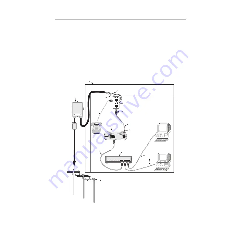
Figure 3-4 shows an example of a residential, small office/home office 
(SOHO), or small business customer using the ADSL to achieve high-
speed access to the Internet. A multiport Ethernet hub is connected 
to the DSL Modem. The hub allows multiple PCs to share bandwidth 
to and from the DSL Modem. The Ethernet cable (straight) shown in 
Figure 3-4 is not included in the DSL Modem package. The wiring 
procedure for multiple PCs is similar to the procedure for Spare 
Inside Wire and New Inside Wire.


Note: 


An Ethernet cable (straight) must be used whenever connecting 

the DSL Modem to a hubbing device.


Figure 3-4:  Multi-User High-Speed Internet Access

m0493.4

Network Interface

Device (NID)

DSL Splitter Inside

Data Wire

Ethernet Cable

(Straight)

To

Telephone

Company

Voice

Wire

*Asterisk denotes item included in the DSL modem package.

Inside Wire (CAT 3)

RJ-11
Cable

ADSL Cable
(Straight)*

DSL Modem*

New Wall Plate

with RJ-11 and

RJ-45 Jacks

Multiple PC Application Using DSL Modem

RJ-45
Connector

RJ-11
Connector

Ethernet

Cables

(Straight)

LINE

LINE

DATA

DATA

G

R

G

R

Hub

Summary of Contents for DSL Modem

Page 1: ......

Page 2: ......

Page 3: ...roduced in any form without written permission of FNC Information contained in this document is FNC Propriety and Confidential and is for use by FNC authorized recipients only Copyright Fujitsu Network Communications Inc All Rights Reserved Copyright Notice DSL Modem Installation Guide Issue 2 September 1998 FJTU 320 600 900 ...

Page 4: ......

Page 5: ... not occur in a particular installation If this equipment does cause harmful interference to radio or television reception which can be determined by turning the equipment off and on the user is encouraged to try to correct the interference by one or more of the following measures Reorient or relocate the receiving antenna Increase the separation between the equipment and receiver Connect the equi...

Page 6: ......

Page 7: ... DSL Modem 2 1 Mounting the DSL Modem 4 2 2 DSL Modem Front Panel Description 5 2 3 DSL Modem Rear Panel Description 6 3 Connecting the DSL Modem to the Splitter 3 1 Overview 7 3 2 Inside Wiring Procedures 8 3 3 Multiple PCs Wiring Procedure 13 4 Turn Up and Operation 4 1 Connecting the Power Supply Convertor 14 4 2 Starting the Modem 14 ...

Page 8: ......

Page 9: ...telecommuting and the Internet grows the search for methods of delivering larger amounts of data over the existing copper telephone wire increases ADSL technology is one method of delivery ADSL technology uses advanced digital modulation to transmit data at high speeds over standard telephone wiring This technology can download data at 8 Mbps and upload data at up to 768 kb s The DSL Modem is part...

Page 10: ...or continuous telephone service even if the power fails The DSL Modem encodes the data sent from your PC to a corresponding DSL Modem located at your local telephone company 1 2 Unpacking Instructions Before unpacking make a preliminary inspection of the shipping box Any evidence of damage should be noted and reported immediately to the customer support center Note The customer support information...

Page 11: ...Ethernet or null crossover cable ASDL cable straight Power supply convertor m0437 2 Part FC9660RA12 P O W E R M O D E M D A TA DSL Modem Ethernet Crossover Cable m0487 2 Part FC9660CB23 ADSL Cable Straight m0488 2 Part FC9660CB22 m0494 3 Part FC9660PS11 Power Supply Convertor ...

Page 12: ...s shelves or mounted on walls The wall mounting requires two wall anchors not included The feet located on the bottom of the modem are used to hang the unit on the wall anchors Figure 2 1 shows a diagram of how to mount the DSL Modem Figure 2 1 DSL Modem Mounting Holes m0435 Feet for wall mounting ...

Page 13: ...he lights on the front panel of the DSL Modem Figure 2 2 DSL Modem Modem Lights Description POWER Indicates if power is applied to the modem MODEM Indicates a valid link with the phone company s equipment DATA Indicates if the ADSL rate is operating at efficient capacity m0491 P O W E R M O D E M D A T A ...

Page 14: ... Description Power Multi pin outlet for connection of the power supply wall transformer This cable is supplied in the DSL Modem package DATA RJ 45 connector for the Ethernet crossover cable This cable is supplied in the DSL Modem package LINE RJ 11 and RJ 45 connector for a connection to the RJ 45 wall plate using the ADSL cable straight This cable is supplied in the DSL Modem package m0436 2 LINE...

Page 15: ...ta interior wire paths Before connecting the wires from the NID to the DSL Modem verify that the inside wire pair serving the DSL Modem has an isolated path from the NID to the modem Do not connect a telephone to the same wire pair In some instances it may be necessary to reroute the inside wire away from noise sources such as appliances fluorescent lighting televisions light dimmers and other ele...

Page 16: ...iginal inside wire then see the section Spare Inside Wire If you are using new inside wire cable CAT 3 or CAT 5 for the data then see the section New Inside Wire See Figure 3 1 for a diagram of the NID data and voice outputs Note From the NID open the latch door to the data module You will see four colored screws Note the coloring of the wire that is connected to the green and red screws For this ...

Page 17: ...data latch connect the same black wire to the green pin of the new wall jack Repeat this step for the voice wire 4 Connect the RJ 45 end of the ADSL cable straight to the RJ 45 jack on the wall plate Connect the RJ 11 end of the ADSL cable straight to the LINE connector on the modem The LINE connection is located on the back panel of the DSL Modem The ADSL cable straight is included in the DSL Mod...

Page 18: ...ction LINE LINE DATA DATA m0492 3 Network Interface Device NID DSL Splitter Inside Data Wire Ethernet Crossover Cable To Telephone Company Voice Wire Asterisk denotes item included in the DSL modem package Inside Wire CAT 3 G R G R RJ 11 Cable ADSL Cable Straight DSL Modem New Wall Plate with RJ 11 and RJ 45 Jacks 6 4 3 5 2 1 Spare Inside Wire Connections RJ 45 Connector RJ 11 Connector ...

Page 19: ... plate near your PC 3 Connect the wires attached to the data voice green and red screws on the NID to the green and red pins on the wall jack For example if a black wire is connected to the green screw on the data connect the same black wire to the green pin on the new RJ 45 wall jack 4 Repeat Step 3 for the voice wiring 5 Connect the RJ 45 end of the ADSL cable straight to the RJ 45 jack on the w...

Page 20: ...gure 3 3 New Inside Wire Connections LINE LINE DATA DATA m0489 3 Network Interface Device NID DSL Splitter Inside Ethernet Crossover Cable To Telephone Company Voice Wire Asterisk denotes item included in the DSL modem package New Inside Wire CAT 3 or CAT 5 for Data ADSL G R RJ 11 Cable ADSL Cable Straight DSL Modem Existing Inside Wire CAT3 Existing Wall Plate with RJ 11 Jack New Wall Plate with ...

Page 21: ... multiple PCs is similar to the procedure for Spare Inside Wire and New Inside Wire Note An Ethernet cable straight must be used whenever connecting the DSL Modem to a hubbing device Figure 3 4 Multi User High Speed Internet Access m0493 4 Network Interface Device NID DSL Splitter Inside Data Wire Ethernet Cable Straight To Telephone Company Voice Wire Asterisk denotes item included in the DSL mod...

Page 22: ...een the DSL Modem and the telephone company is established the telephone company checks the software version against the DSL Modem When this is happening the POWER light is on and the MODEM light blinks If the software versions are incompatible the DSL Modem will automatically receive a software upgrade of the appropriate version During a software upgrade the POWER light stays on and the DATA and ...

Page 23: ...ceive a software upgrade from the phone company If the modem stays in this state for more than 10 minutes an error has occurred Contact the customer support center Receiving a software upgrade if needed If the modem stays in this state for more than 10 minutes an error has occurred Contact the customer support center Software upgrade complete Modem is connected and communicating with the phone com...

Page 24: ...BACK COVER BLANK PAGE ...

Reviews: