Brief description of mainboard
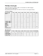
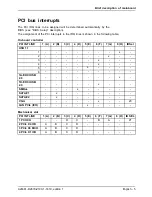
PCI bus interrupts
The PCI IRQ lines to be assigned will be determined automatically by the
BIOS (see "BIOS Setup" description).
The assignment of the PCI interrupts to the IRQ lines is shown in the following table:
On-board controller
PCI INT LINE
1 (A)
2 (B)
3 (C)
4 (D)
5 (E)
6 (F)
7 (G)
8 (H)
IDSel
USB 1.1
-
1
-
-
-
-
-
-
-
x
-
2
-
-
-
-
-
-
x
-
-
3
-
-
-
-
-
x
-
-
-
4
-
-
-
-
-
x
-
-
-
5
-
-
-
-
x
-
-
-
-
6
-
-
-
-
-
-
-
-
-
1A-EHCI USB
2.0
-
-
-
-
-
-
-
x
-
1D-EHCI USB
2.0
-
-
-
-
-
x
-
-
-
SMBus
-
-
-
x
-
-
-
-
-
SATA #1
-
x
-
-
-
-
-
-
-
SATA #2
-
x
-
-
-
-
-
-
-
VGA
-
-
-
-
-
x
-
-
23
LAN PCIe (ICH)
-
-
-
-
x
-
-
-
-
Mechanical slot
PCI INT LINE
1 (A)
2 (B)
3 (C)
4 (D)
5 (E)
6 (F)
7 (G)
8 (H)
ID SEL
1 PCI ICH
-
-
D
C
-
B
A
-
21
2 PCIe X4 ICH
A
B
C
D
-
-
-
-
-
3 PCIe X8 MCH
A
B
C
D
4 PCIe X1 ICH
A
B
C
D
-
-
-
-
-
A26361-D2679-Z100-1-7419, edition 1
English - 5


