background image

System upgrades


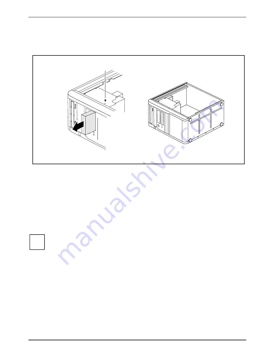
Installing and removing the floppy disk drive 


Open the casing (see "Opening the casing"). 


2

1


Remove the data and power supply connectors from the floppy disk drive. 


Remove the screws (1) on the right side of the floppy disk drive. 


Slide the floppy disk drive out of the casing in the direction of the arrow (2). 


Slide the new floppy disk drive into the case opposite the direction of the arrow (2). 


Fasten the floppy disk drive with the screws (1). 


Fit the data and power supply connectors to the floppy disk drive. Make sure the polarity is 
correct. 


Close the casing (see "Closing the casing"). 


It may be necessary to modify the entry for the drive in the 

BIOS Setup

i


48 

Fujitsu Technology Solutions 

Summary of Contents for CELSIUS W380

Page 1: ...Operating Manual System CELSIUS W380 CELSIUS W480 ...

Page 2: ... http ts fujitsu com For automatic driver updates go to http support de ts fujitsu com de support index html Should you have any technical questions please contact our Hotline Service Desk see the Service Desk list or visit http ts fujitsu com support servicedesk html Your sales partner Your sales office We hope you really enjoy using your new Fujitsu system ...

Page 3: ......

Page 4: ...ject to modifications and delivery subject to availability Any liability that the data and illustrations are complete actual or correct is excluded Designations may be trademarks and or copyrights of the respective manufacturer the use of which by third parties for their own purposes may infringe the rights of such owner For further information see http ts fujitsu com terms_of_use html Order No Fu...

Page 5: ...CELSIUS W380 CELSIUS W480 Operating Manual Your CELSIUS 1 Important notes 3 Preparing for use 5 Operation 15 Troubleshooting and tips 23 System upgrades 31 Technical data 55 Index 57 ...

Page 6: ...s Incorporated All other trademarks referenced are trademarks or registered trademarks of their respective owners whose protected rights are acknowledged Copyright Fujitsu Technology Solutions GmbH 2009 All rights including rights of translation reproduction by printing copying or similar methods in part or in whole are reserved Offenders will be liable for damages All rights reserved particularly...

Page 7: ...ng on monitor and device 12 Installing the software 13 Operation 15 Switch the device on 15 Switching off the device 15 Indicators provided by the device 16 Keyboard 17 Important keys and key combinations 17 Settings in BIOS Setup 19 Property and data protection 19 Mechanical casing lock optional 19 Anti theft protection and lead sealing 20 BIOS setup security functions 20 Access authorization via...

Page 8: ... board 40 Installing a board 40 Removing boards 42 Low profile boards 44 Installing and removing drives 45 Removing an accessible drive 45 Installing an accessible drive 47 Installing and removing the floppy disk drive 48 Installing and removing the hard disk drive 49 Removing a hard disk drive 49 Hard disk drive installing 50 Mainboard expansions 52 Main memory upgrading 52 Processor replacing 52...

Page 9: ...he BIOS Setup also allow you to protect your data by means of passwords In addition systems with a SmartCard reader offer additional protection Under certain operating systems DeskUpdate allows you to quickly and easily install the latest drivers and operating system upgrades with just a few mouse clicks DeskUpdate is contained on the Drivers Utilities CD DVD Further information on this device is ...

Page 10: ...l damage This symbol indicates important information which is required to use the system properly i Texts which follow this symbol describe steps that must be performed in the order shown indicates screen outputs This font This font indicates programme names commands or menu items Quotation marks indicate names of chapters data carriers and terms that are being emphasised 2 Fujitsu Technology Solu...

Page 11: ...e remove the power plug from the power socket Replace the lithium battery on the mainboard in accordance with the instructions in the Replacing the lithium battery chapter Transporting the device Transport all parts separately in their original packaging or in a packaging which protects them from knocks and jolts to the new site Do not unpack them until all transportation manoeuvres are completed ...

Page 12: ...ause harmful interference to radio communications However there is no guarantee that interference will not occur in a particular installation If this equipment does cause harmful interference to radio or television reception which can be determined by turning the equipment off and on the user is encouraged to try to correct the interference by one or more of the following measures Reorient or relo...

Page 13: ... new device into operation for the first time Select a location for device and set up device Connect the monitor mouse and keyboard Check the voltage at the mains outlet and connect the device to an electrical outlet Switch the device on You will learn more about the individual steps in the following sections External devices If you have received other devices in addition to your device e g a prin...

Page 14: ...ome vibrations and noises may occur To prevent this a distance of at least 10 mm should be maintained from other devices on casing sides without ventilation surfaces In addition we recommend placing the device on support feet as these buffer vibrations External devices connecting Read the documentation on the external device before connecting it With the exception of USB devices always remove all ...

Page 15: ...re located on the front and back of the device The ports available on your device depend on the configuration level you have selected The standard ports are marked with the symbols shown below or similar Detailed information on the location of the connections is provided in the manual for the mainboard Keyboard port purple Parallel port Printer burgundy 1 Serial port 1 teal or turquoise 2 Serial p...

Page 16: ...covered and without function In this case only use the external monitor ports of the display adapter in one of the module slots 2 1 2 1 Monitor ports of the mainboard 2 External monitor ports of the display adapter Follow the instructions contained in the monitor manual to prepare the monitor for operation e g connecting cables Connect the data cable to a suitable monitor port of the device VGA DV...

Page 17: ...ting the keyboard Depending on the equipment level selected your device will be supplied with a USB keyboard or a PS 2 keyboard Connecting a USB keyboard Use the supplied keyboard cable only Plug the rectangular connector of the keyboard cable into the rectangular socket on the underside of the keyboard Insert the flat rectangular USB plug of the keyboard cable into a USB port of the device Connec...

Page 18: ...nternet or will be supplied on a data carrier Connecting external devices to the USB ports You can connect a wide range of external devices to the USB ports e g printer scanner modem or keyboard i USB devices are hot pluggable This means you can connect and disconnect devices while your operating system is running Additional information can be found in the documentation for the USB devices Connect...

Page 19: ...ions about these settings When you switch on the device for the first time the supplied software is installed and configured Plan a reasonable amount of time for this as this process must not be interrupted Once the installation has been started the device must not be switched off unless the installation has been completed During installation the device may only be rebooted when you are requested ...

Page 20: ... switch on the back of the device in addition to the ON OFF button on the right hand side As a result there are different ways to switch on the two variants i Switching on the device with main power switch 0 1 I I Device is ready to operate 0 Device is off Switch the device on with the main power switch 1 on the back of the device Press the ON OFF switch 2 on the right hand side of the device The ...

Page 21: ...tarts Installing the software During installation follow the on screen instructions Consult the operating system manual if anything is unclear about the input data requested by the system i You will find further information about the system drivers utilities and updates on the Drivers Utilities CD DVD supplied Fujitsu Technology Solutions 13 ...

Page 22: ...Preparing for use 14 Fujitsu Technology Solutions ...

Page 23: ... Exit function If the operating system does not automatically switch the device into energy saving mode or switch it off press the ON OFF switch If the device is ready to use the device consumes a minimum of energy Switch the device off at the main switch if present The device no longer uses any power The main switch and the ON OFF switch do not disconnect the device from the mains voltage To comp...

Page 24: ...e appears on the LCD as soon as the workstation is in energy saving mode The workstation can be switched on with the ON OFF switch Hard disk appears on the LCD as soon as the hard disk is accessed X Error appears on the LCD if there is a hardware error in the workstation or if a critical hardware state is reached e g fan failure high temperature You can use DeskView to get detailed information on ...

Page 25: ...board is an example and may differ from the model you use i Important keys and key combinations The description of the following keys and key combinations applies to Microsoft operating systems Details of other keys and key combinations can be found in the documentation of the relevant application programme ON OFF switch optional Depending on the setting in the BIOS Setup the system can be switche...

Page 26: ...er on the key Q Alt Gr Num key Switches the numeric key pad between number mode Num indicator lights up and editing mode Num indicator does not light up Num When the Num Lock indicator is lit the digit and comma keys are active When the Num Lock indicator is not lit the cursor control functions are active in the Numeric keypad Ctrl key starts key combination actions The Ctrl key is also called Con...

Page 27: ...e functions and mechanical locking offer a broad range of functions for protecting your device and your personal data from unauthorised access You can also combine these functions Mechanical casing lock optional With the casing lock you can mechanically lock the casing to prohibit unauthorised persons from opening it The keys can be found on the rear panel of your device 2 1 Locking the casing Tur...

Page 28: ...S setup security functions The Security menu in BIOS Setup offers you various options for protecting your personal data against unauthorised access e g Preventing unauthorised access to the BIOS Setup Preventing unauthorised system access Preventing unauthorised access to the settings of boards with their own BIOS Preventing system booting from the diskette drive Virus warnings activating Diskette...

Page 29: ...same permissions More information on SystemLock i If you also want to use other security software in addition to SystemLock e g SMARTY please read the documentation on your security software beforehand SystemLock permissions You can initialise a SmartCard with one of the following permissions System The system starts following entry of the user PIN You can change the user PIN You can open and chan...

Page 30: ...Operation 22 Fujitsu Technology Solutions ...

Page 31: ... Contact your sales outlet or our customer service centre Help if problems occur Should you ever have a problem with your computer that you cannot solve yourself in many cases you can solve it quickly using the SystemDiagnostics program pre installed on your computer To start the SystemDiagnostics program click Start Programs Fujitsu SystemDiagnostics If a problem is detected during the test run t...

Page 32: ...as not been switched on with the ON OFF switch Press the ON OFF switch again System crash Press the ON OFF switch for at least 4 seconds until the device switches off The operating system is not shut down properly in the process Error messages are therefore possible the next time the system is booted 24 Fujitsu Technology Solutions ...

Page 33: ...nual supplied with your monitor Power cable is not connected Switch off the monitor and the device Check that the monitor power cable is properly connected to the monitor and to a grounded mains outlet or to the monitor socket of the device Check that the device power cable is properly plugged into the device and a grounded mains outlet Switch on the monitor and the device Monitor cable is not con...

Page 34: ...pears press F8 Select Safe Mode or Safe Mode with Network Set the correct values for the connected monitor as described in the operating manual of the monitor by selecting Start Settings Control Panel Display and then the Appearance Themes Settings tabs Wrong monitor has been set under Window 7 Restart the device Press F8 while the system is booting Either the Windows Advanced Start Options menu o...

Page 35: ...rogramme is started Detailed information can be found in the user guide for the mouse and application programme The floppy disk cannot be read or written Cause Troubleshooting The write protection of the floppy disk or the floppy disk drive is activated Check that the write protection of the floppy disk or the floppy disk drive is activated refer to the BIOS Setup manual and if necessary to the ma...

Page 36: ...y Error messages on the screen Error messages and their explanation are contained in the manual for the mainboard in the documentation for the programmes used Installing new software When installing programmes or drivers important files may be overwritten and modified You should backup your hard disk prior to installation so that you can still access the original data in the event of any problems ...

Page 37: ... applications running at once you may experience problems due to a lack of system resources Close unnecessary applications or Run the applications in a different order Other manuals Other manuals are provided as PDF files on the Drivers Utilities CD DVD Fujitsu Technology Solutions 29 ...

Page 38: ...Troubleshooting and tips 30 Fujitsu Technology Solutions ...

Page 39: ... supplied documentation before installing new drives and or boards Refer to the manual for the mainboard before making any extensions to the mainboard Information about boards Take care with the locking mechanisms catches and centring pins when you are replacing boards or components on boards To prevent damage to the board or the components and conductors on it please take care when you insert or ...

Page 40: ...otes chapter Disconnect the mains plug from the mains outlet Only insert the power plug after you have closed the casing On devices with a casing lock Unlock the casing Remove any plugged in wires which are in the way Lay the device on its side 2 1 Pull the locking device 1 and swivel the side part in the direction of the arrow 2 32 Fujitsu Technology Solutions ...

Page 41: ... part in the guide rail on the lower part of the casing Swivel the side part in the direction of the arrow 1 until it engages On devices with a casing lock Lock the casing Reconnect the cables that you disconnected before Fujitsu Technology Solutions 33 ...

Page 42: ... 1 1 2 Open the casing see Opening the casing Place the removed side part on a flat surface with the inside facing upwards Press the catch in the direction of the arrow 1 Carefully thread the locking device out of the side part in the direction of the arrow 2 34 Fujitsu Technology Solutions ...

Page 43: ...r so that the outside faces upwards Guide the locking device with the casing lock in the direction of the arrow 1 into the side part Press the catch in the direction of the arrow 2 and at the same time press the locking device into the side part 3 until the catch engages Fujitsu Technology Solutions 35 ...

Page 44: ...e drive cage Open the casing see Opening the casing 2 1 Unscrew the knurled screw 1 Fold open the drive cage 2 i Thanks to the integrated torque controller the drive cage will stop in any position 36 Fujitsu Technology Solutions ...

Page 45: ...es Closing the drive cage 2 1 Fold down the drive cage 1 Be careful that no wires become trapped Secure the drive cage with the knurled screw 2 Close the casing see Closing the casing Fujitsu Technology Solutions 37 ...

Page 46: ...Fold up the drive cage see Opening the drive cage Unhook the wires from the holder on the ventilation duct Remove any plugged in wires which are in the way Unlock the ventilation duct by pressing locking hooks in the direction of the arrow 1 Keep pressing the locking hook and pull the ventilation duct in the direction of the arrow 2 out from the casing 38 Fujitsu Technology Solutions ...

Page 47: ...tion duct into the corresponding slots in the casing Press the ventilation duct into the casing in the direction of the arrow 1 so that the locking hook is felt to engage Reconnect the cables that you disconnected before Hook the wires into the holder on the ventilation duct Fold down the drive cage see Closing the drive cage Close the casing see Closing the casing Fujitsu Technology Solutions 39 ...

Page 48: ...for the mainboard Boards may already be installed on shipment Installing a board Open the casing see Opening the casing Fold up the drive cage see Opening the drive cage 1 2 Press on the curved part of the retaining clip 1 Pull the slot cover out of the slot in the direction of the arrow 2 Do not throw away the slot cover For cooling protection against fire and in order to comply with EMC regulati...

Page 49: ...e drive cage see Closing the drive cage Close the casing see Closing the casing If you have installed or removed a board please check the relevant PCI slot settings in the BIOS Setup If necessary change the settings Further information is provided in the PCI board documentation Information about the installation of low profile boards can be found in the section Low profile boards i Fujitsu Technol...

Page 50: ...ing clip 1 If you have also secured the board with an additional screw remove the screw now Pull the board out of the slot in the direction of the arrow 2 Place the board into appropriate packaging For cooling protection against fire and in order to comply with EMC electromagnetic compatibility regulations you must refit the slot cover 2 1 Push the slot cover into the slot 1 42 Fujitsu Technology ...

Page 51: ...ee Closing the drive cage Close the casing see Closing the casing i If you have installed or removed a PCI board please check the relevant PCI slot settings in the BIOS Setup If necessary change the settings Further information is provided in the PCI board documentation Fujitsu Technology Solutions 43 ...

Page 52: ...ard slot cover and undo the screw Do not dispose of the slot cover If you remove the board again you must reinstall the slot cover cooling fire protection or EMC regulations to be complied with Mounting slot adapter Fit the slot adapter on the slot cover of the low profile board 1 and screw it on 2 2 1 Now you can install the low profile board in a suitable slot like a normal board see Installing ...

Page 53: ...cessible drives are e g hard disk drives Removing an accessible drive Open the casing see Opening the casing 1 2 Pull the data and the power supply connectors from the drive Press on the retaining clip 1 and at the same time slide it down slightly 2 Open the retaining clip Slide the drive out of the bay in the direction of the arrow 3 from behind The drive now protrudes slightly out of the casing ...

Page 54: ...y slide in module as far as it will go into the casing 1 Press on the retaining clip 2 and at the same time slide it up slightly Close the casing see Closing the casing It may be necessary to modify the entry for the drive in the BIOS Setup i 46 Fujitsu Technology Solutions ...

Page 55: ...ulations you must refit the empty slide in module if you remove the drive again later Adjust the required settings on the drive if necessary on already installed drives as well 2 1 Slide the accessible drive into the casing as far as the stop 1 Plug the data and the power supply connectors into the drive Make sure the polarity is correct Press on the retaining clip 2 and at the same time slide it ...

Page 56: ...he floppy disk drive out of the casing in the direction of the arrow 2 Slide the new floppy disk drive into the case opposite the direction of the arrow 2 Fasten the floppy disk drive with the screws 1 Fit the data and power supply connectors to the floppy disk drive Make sure the polarity is correct Close the casing see Closing the casing It may be necessary to modify the entry for the drive in t...

Page 57: ... EasyChange rails mounted on the hard disk 1 and pull the hard disk drive out of the drive cage in the direction of the arrow 2 Disconnect all cables connected to the drive data cable power supply cable Pull the EasyChange rails off the hard disk drive It may be necessary to modify the entry for the drive in the BIOS Setup i Fold down the drive cage see Closing the drive cage Fujitsu Technology So...

Page 58: ...cage see Opening the drive cage EasyChange rails for any additional hard disk drives are mounted on the drive cage i Secure the EasyChange rails on the side of the hard disk by inserting the upper pins of the EasyChange rail in the corresponding holes of the hard disk Connect the cables to the hard disk drive 50 Fujitsu Technology Solutions ...

Page 59: ...into the drive cage Check that the component side of the hard disk drive faces inwards towards the casing Fold down the drive cage see Closing the drive cage Close the casing see Closing the casing It may be necessary to modify the entry for the drive in the BIOS Setup i Fujitsu Technology Solutions 51 ...

Page 60: ...the mainboard Fold down the drive cage see Closing the drive cage Close the casing see Closing the casing Processor replacing Open the casing see Opening the casing Fold up the drive cage see Opening the drive cage Remove the ventilation duct see Removing ventilation duct Replace the processor as it is described in the manual for the mainboard Install the ventilation duct see Installing ventilatio...

Page 61: ...or with a type recommended by the manufacturer Do not throw lithium batteries into the household waste They must be disposed of in accordance with local regulations concerning special waste Make sure that you observe the correct polarity when replacing the lithium battery The plus pole must be on the top The lithium battery holder exists in different designs that function in the same way 2 3 1 2 3...

Page 62: ...System upgrades 54 Fujitsu Technology Solutions ...

Page 63: ...mm Weight In basic configuration approx 11 kg Environmental conditions Environment class 3K2 DIN IEC 721 part 3 3 Environment class 2K2 DIN IEC 721 part 3 2 Temperature Operating 3K2 15 C 35 C Transport 2K2 25 C 60 C Condensation must be avoided during operation Clearance required to ensure adequate ventilation Without air vents min 10 mm With air vents min 200 mm The data sheets of these devices ...

Page 64: ...Technical data 56 Fujitsu Technology Solutions ...

Page 65: ...cting USB mouse 9 Contents of delivery 5 Ctrl Alt Del 18 Cursor keys 17 D Data protection 19 Data technical 55 Date not correct 28 Device Anti theft protection 20 cannot boot 24 checking rated voltage 11 cleaning 3 closing 33 connecting 6 11 connecting devices 6 indicators 16 lead sealing 20 locking mechanically 19 opening 32 ports 7 setting up 6 switching off 15 switching on 13 switching on for t...

Page 66: ...n 17 18 Keyboard 17 alphanumeric keypad 17 connecting 9 cursor keys 17 function keys 17 numeric keypad 17 Keyboard port 7 9 Keys 17 Ctrl key 18 Ctrl Alt Del 18 Menu key 18 Shift key 18 Start key 18 L LAN port 7 LCD 16 Lead sealing 20 Line in 7 Line out 7 Lithium battery 52 replacing 53 Lock 19 Locking device removing 34 Low profile boards 44 mounting slot adapter 44 removing slot adapter 44 M Main...

Page 67: ...measures 19 Serial port 7 10 connecting devices 10 settings 10 Setup see BIOS Setup Signs and symbols 2 SmartCard reader operating 21 Software installing 12 14 new installation 28 Summer time 28 Surface 55 Switch the device on 15 Switching the device off devices with main power switch 15 Switching the device on devices with main power switch 15 System expansion 31 System resources insufficient 29 ...

Reviews: