


En-4
Table 1
Flare nut tightening torque
Flare nut
Diameter (mm)
x Torque (N • m
)
6.35 mm dia.
17 x
16 ~ 18
12.7 mm dia.
26 x 49 ~ 61
Table 2
Pipe outside diameter
Pipe outside
diameter
A (mm)
Flare tool for
R410A, clutch type
Conventional (R22) Flaring tool
Clutch type
Wing nut type
ø 6.35 mm (1/4")
0 to 0.5
1.0 to 1.5
1.5 to 2.0
ø 12.7 mm (1/2")
0 to 0.5
1.0 to 1.5
1.5 to 2.0
CAUTION
Fasten a
fl
are nut with a torque wrench as instructed in this manual. If fastened too
tight, the
fl
are nut may be broken after a long period of time and cause a leakage of
refrigerant.
During installation, make sure that the refrigerant pipe is attached
fi
rmly before you run
the compressor. Do not operate the compressor under the condition of refrigerant piping
not attached properly with 2-way or 3-way valve open. This may cause abnormal pres-
sure in the refrigeration cycle that leads to breakage and even injury.
5.6. Air purge
Always use a vacuum pump to purge the air.
Refrigerant for purging the air is not charged in the outdoor unit at the factory.
Close the high pressure side valve of the gauge manifold fully and do not operate it during
the following work.
CAUTION
Refrigerant must not be discharged into atmosphere.
After connecting the piping , check the joints for gas leakage with gas leak detector.
(1) Check if the piping connections are secure.
(2) Check that the stems of 2-way valve and 3-way valve are closed fully.
(3) Connect the gauge manifold charge hose to the charging port of the 3-way valve (side
with the projection for pushing in the valve core).
(4) Open the low pressure side valve of the gauge manifold fully.
(5) Operate the vacuum pump and start pump down.
(6) Slowly loosen the
fl
are nut of the 3-way valve and check if air enters, then retighten
the
fl
are nut.
(When the
fl
are nut is loosened the operating sound of the vacuum pump changes
and the reading of the compound pressure gauge goes from minus to zero.)
(7) Pump down the system for at least 15 minutes, then check if the compound pressure
gauge reads -0.1 MPa (-76 cmHg, -1 bar).
(8) At the end of pump down, close the low pressure side gauge of the gauge manifold
fully and stop the vacuum pump.
(9) Slowly loosen the valve stem of the 3-way valve. When the compound pressure
gauge reading reaches 0.1-0.2 MPa, retighten the valve stem and disconnect the
charge hose from the 3-way valve charging port.
(If the stem of the 3-way valve is opened fully before the charge hose is disconnect-
ed, it may be dif
fi
cult to disconnect the charge hose.)
(10) Fully open the valve stems of the 2-way valve and 3-way valve using a hexagon
wrench. (After the valve stem begins to turn, turn it with a torque of less than
2.9 N • m (30 kgf • cm) until it stops turning.)
(11) Firmly tighten the 2-way valve and 3-way valve blank cap and the charging port cap.
3-way valve
2
-way valve
Charging
port cap
Vacuum pump
Charge
hose
Charge hose
Charging port
Blank cap
Valve stem
Flare nut
Compound pressure gauge
Gauge manifold
Pressure gauge
High
pressure
side valve
(closed)
Low
pressure
side
valve
-0.1 MPa
(-76 cmHg
-1 bar)
Tightening torque
Blank cap (2-way valve)
20.0 to 25.0 N • m (200 to 250 kgf • cm)
Blank cap (3-way valve)
28.0 to 32.0 N • m (280 to 320 kgf • cm)
Charging port cap
12.5 to 16.0 N • m (125 to 160 kgf • cm)
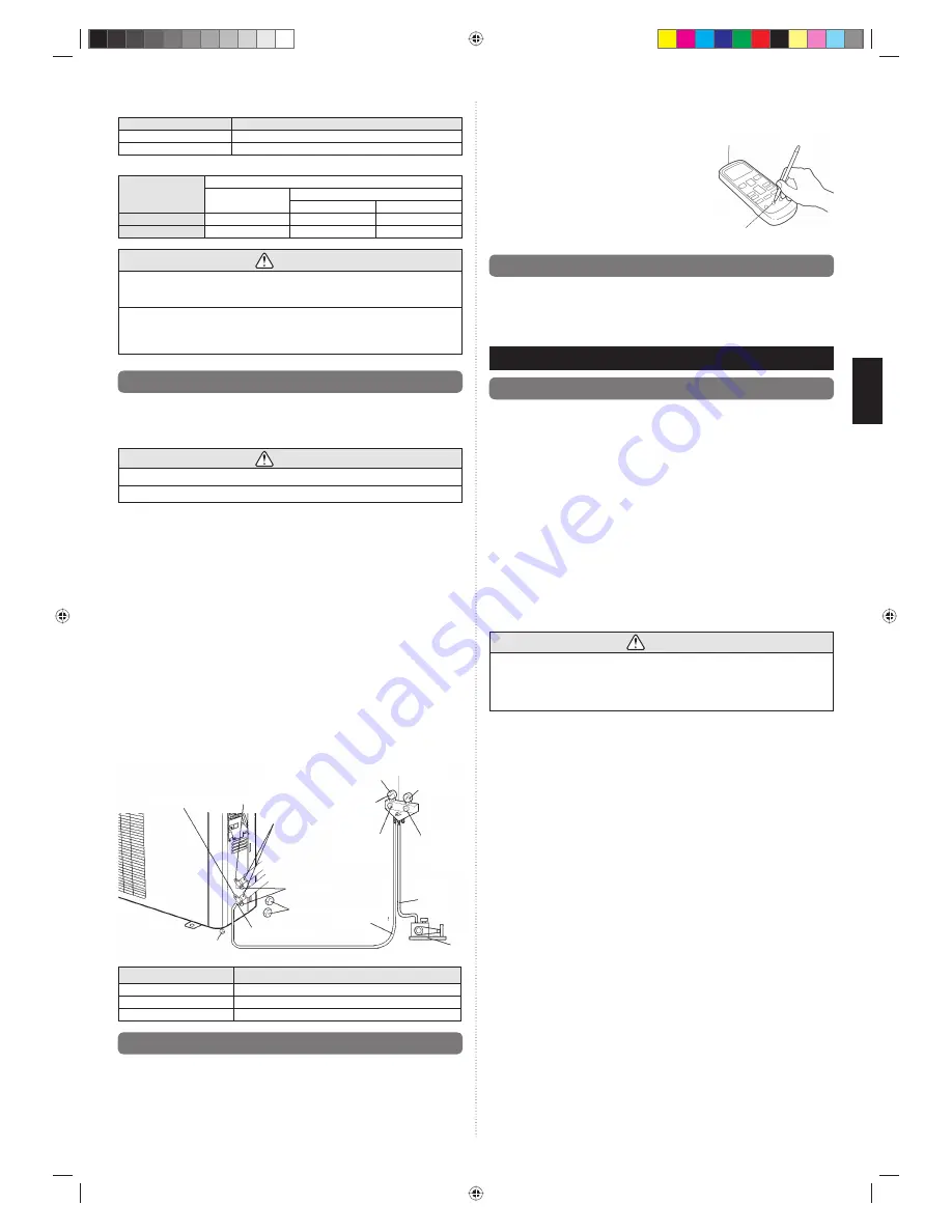
5.7. TEST RUN
•
Perform test operation and check items below.
•
For the test operation method, refer to the operating manual.
•
The outdoor unit, may not operate, depending on the room temperature. In this case,
press the test run button on the remote controller while the air conditioner is running,
(Point the transmitter section of the remote controller toward the air conditioner and
press the test run button with the tip of a ball-point pen, etc.)
•
To end test operation, press the remote controller START/STOP button.
(When the air conditioner is run by pressing the test run button, the OPERATION indica-
tor lamp and TIMER indicator lamp will simultaneously
fl
ash slowly.)
OUTDOOR UNIT
(1) Is there any abnormal noise and vibration during
operation?
(2) Will noise, wind, or drain water from the unit
disturb the neighbors?
(3) Is there any gas leakage?
5.8. CUSTOMER GUIDANCE
Explain the followings to the customer in accordance with the operating manual:
(1) Starting and stopping method, operation switching, temperature adjustment, timer,
air
fl
ow switching, and other remote controller operations.
(2) Air
fi
lter removal and cleaning, and how to use the air
fl
ow direction louvers.
(3) Give the operating and installation manuals to the customer.
6. PUMP DOWN
6.1. Pump down
PUMP DOWN OPERATION (FORCED COOLING OPERATION)
To avoid discharging refrigerant into the atmosphere at the time of relocation or disposal,
recover refrigerant by doing the cooling operation or forced cooling operation according
to the following procedure. (When the cooling operation cannot start in winter, and so on,
start the forced cooling operation.).
(1) Do the air purging of the charge hose by connecting the charging hose of gauge mani-
fold to the charging port of 3-way valve and opening the low-pressure valve slightly.
(2) Close the valve stem of 2-way valve completely.
(3) Start the cooling operation or following forced cooling operation. Keep on pressing the
MANUAL AUTO button of the indoor unit for more than 10 seconds. The operation in-
dicator lamp and timer indicator lamp will begin to flash simultaneously during test run.
(The forced cooling operation cannot start if the MANUAL AUTO button is not kept on
pressing for more than 10 seconds.)
(4) Close the valve stem of 3-way valve when the reading on the compound pressure
gage becomes 0.05~0 Mpa(0.5~0 kg/cm
2
).
(5) Stop the operation.
• Press the START/STOP button of the remote control unit to stop the operation.
• Press the MANUAL AUTO button when stopping the operation from indoor unit side. (It
is not necessary to press on keeping for more than 10 seconds.)
CAUTION
During the pump-down operation, make sure that the compressor is turned off before
you remove the refrigerant piping.
Do not remove the connection pipe while the compressor is in operation with 2-way or
3-way valve open. This may cause abnormal pressure in the refrigeration cycle that
leads to breakage and even injury.
Transmitter section
Test
run
button
9377863119_IM.indb 4
9377863119_IM.indb 4
1/20/2011 6:10:41 PM
1/20/2011 6:10:41 PM


