background image

2008.01.21

1

H x W x D

600 x 740 x 200  mm

MEASUREMENT

DIMENSIONS

Gross / Net

17 kg  /  14 kg

WEIGHT

SPECIFICATIONS

TYPE

Cooling & heating inverter

MODEL NAME

INDOOR UNIT

AGYF14LAC

AGYF12LAC

AGYF09LAC

Cooling
Heating

MOISTURE REMOVAL

1.5 L/hr

AIR CIRCULATION HIGH

650 m3/hr

530 m3/hr

650 m3/hr

530 m3/hr

0.7 L/hr

500 m3/hr
600 m3/hr

1.1 L/hr

FAN MOTOR

POWER SOURCE

230 V

230 V

230 V

High speed

1,330  /  1,120 r.p.m.

Cooling

(upper fan / lower fan)

Med speed

1,100  /  930 r.p.m.

Low speed

890  /  750 r.p.m.

Quiet

660  /  560 r.p.m.

High speed

1,330  /  1,120 r.p.m.

Heating

(upper fan / lower fan)

Med speed

1,140  /  970 r.p.m.

Low speed

940  /  800 r.p.m.

Quiet

660  /  560 r.p.m.

1,240  /  1,050 r.p.m.

1,050  /  890 r.p.m.

860  /  730 r.p.m.
660  /  560 r.p.m.

1,240  /  1,050 r.p.m.

1,080  /  920 r.p.m.

910  /  770 r.p.m.
660  /  560 r.p.m.

1,120 /  950 r.p.m.

960  /  820 r.p.m.
820  /  700 r.p.m.
660  /  560 r.p.m.

1,120  /  950 r.p.m.
1,000  /  850 r.p.m.

860   /  730 r.p.m.

660  /  560 r.p.m.

ELECTRICAL DATA

Cooling / Heating

Quiet

Low speed

22 dB(A)  /  22 dB(A)

31 dB(A)  /  33 dB(A)

Med speed

High speed

38 dB(A)  /  39 dB(A)

44 dB(A)  /  44 dB(A)

22 dB(A)  /  22 dB(A)

30 dB(A)  /  30 dB(A)

35 dB(A)  /  35 dB(A)

39 dB(A)  /  39 dB(A)

22 dB(A)  /  22 dB(A)

30 dB(A)  /  32 dB(A)

36 dB(A)  /  38 dB(A)

42 dB(A)  /  42 dB(A)

NOISE LEVEL

Summary of Contents for AGYF09LAC

Page 1: ...NSIONS REFRIGERANT SYSTEM DIAGRAM ERROR CONTENTS CIRCUIT DIAGRAM INDOOR PCB CIRCUIT DIAGRAM 11 OUTDOOR PCB CIRCUIT DIAGRAM PARTS indoor unit 16 STANDARD ACCESSORIES 24 PARTS outdoor unit 21 Indoor unit Outdoor unit AGYF09LAC AGYF12LAC AOYA18LAT3 AGYF14LAC AGYF09LAC AGYF12LAC AOYA24LAT3 AGYF14LAC ...

Page 2: ... 750 r p m Quiet 660 560 r p m High speed 1 330 1 120 r p m Heating upper fan lower fan Med speed 1 140 970 r p m Low speed 940 800 r p m Quiet 660 560 r p m 1 240 1 050 r p m 1 050 890 r p m 860 730 r p m 660 560 r p m 1 240 1 050 r p m 1 080 920 r p m 910 770 r p m 660 560 r p m 1 120 950 r p m 960 820 r p m 820 700 r p m 660 560 r p m 1 120 950 r p m 1 000 850 r p m 860 730 r p m 660 560 r p m ...

Page 3: ... g 2 600 g 20 g m 30 m 25 m MIN PIPE LENGTH each unit 5 m 50 m MAX ELEVATION between indoor units 10 m MAX ELEVATION between indoor and outdoor 15 m OUTDOOR UNIT AOYA24LAT3 6 8 kW 8 0 kW 8 5 A 8 8 A 1 94 kW 2 00 kW 3 50 kW kW 4 00 kW kW 3 300 m3 hr COMPRESSOR AND REFRIGERANT FAN MOTOR MEASUREMENT COMPRESSOR TYPE DISCRIMINATION DA150A1F 20NA REFRIGERANT TYPE R410A REFRIGERANT 2 200 g WEIGHT with oi...

Page 4: ...DIMENSIONS INDOOR UNIT unit mm 2008 01 21 3 740 200 600 ...

Page 5: ... Unit mm OUTDOOR UNIT Air Flow 40 900 700 21 9 400 330 31 12 370 650 4 2008 01 21 ...

Page 6: ... valve 3 way valve 3 way valve 2 way valve 2 way valve 2 way valve Heat exchanger Room Thermistor Strainer Expansion valve Expansion valve Expansion valve 4 way valve HEAT COOL Heat exchanger Heat exchanger Heat exchanger Receiver tank Room Thermistor Strainer Strainer Distributor Pipe Thermistor Pipe Thermistor Pipe Thermistor Pipe Thermistor Pipe Thermistor Pipe Thermistor Heat exchanger 2008 01...

Page 7: ...2 1 1 2 3 4 5 6 7 8 9 1 2 3 4 5 6 1 2 3 4 5 6 7 8 9 5 4 3 2 1 4 3 2 1 4 3 2 1 2 1 2 1 2 1 4 3 2 1 4 3 2 1 5 6 5 6 4 3 2 1 5 6 4 3 2 1 5 6 4 3 2 1 5 4 3 2 1 5 4 3 2 1 5 6 CN202 CN203 CN201 CN11 CN17 CN10 CN3 CN12 CN1 CN13 CN18 CN8 CN5 CN6 CN2 TM1 TM5 TM2 THEMAL FUSE 102 TERMINAL 1 2 3 STEP MOTOR DAMPER M M STEP MOTOR UP DOWN STEP MOTOR DAMPER LOCK RIGHT M STEP MOTOR DAMPER LOCK LEFT M FAN MOTOR LOW...

Page 8: ... 1 2 1 2 1 2 1 2 1 2 1 2 3 1 3 4 3 2 1 1 2 3 4 5 6 2 3 1 RED BROWN BLUE ORANGE YELLOW WHITE RED BROWN BLUE ORANGE YELLOW WHITE 1 2 3 4 5 6 7 8 1 2 3 4 5 6 7 8 1 2 4 5 6 7 8 9 1 3 4 5 6 7 8 9 1 2 3 4 5 6 7 8 1 2 3 4 5 6 7 8 1 2 3 4 5 6 1 2 1 2 1 2 3 4 5 6 1 2 3 4 5 6 1 2 3 4 5 6 1 2 3 4 5 6 1 3 4 5 6 7 1 2 4 5 6 7 3 2 1 TERMINAL L N FUSE 250V 25V EMI FILTER 2T LED1 D150 LED3 D152 LED2 D151 F2 FUSE ...

Page 9: ...6 5 4 3 2 1 3 4 5 2 1 3 4 5 2 1 3 4 5 6 2 1 3 4 5 6 2 1 3 4 5 2 1 7 6 5 4 3 2 1 6 5 4 3 2 1 RED WHITE BLACK TM2 22007 TM1 22007 TM5 22007 CN6 B05B XASK CN2 SJH20 05WS CN5 SJH20 06WS CN8 B06B PASK CN12 B05B PASK CN17 B07B XARK CN10 B06B XARK CN11 B09B PASK CN18 B04B PASK CN14 B3B XH CN16 B2B XH CN3 B02B PASK CN1 2P SAN CN13 B7B PH CN201 JB20 09HG CN202 JB20 06HG CN203 JB20 06HG THERMISTOR PIPE TEMP...

Page 10: ... P61 P62 P63 P64 P65 P66 P67 P70 P71 P72 P73 P74 P75 P76 P77 P120 P130 P140 P141 P142 P143 P144 P145 AVREF I C REGC GND AGND EGND I C1 33 I C1 32 I C1 29 I C1 28 I C1 47 I C1 46 VPP I C1 3 CS I C1 26 BEN 5V CS R29 10K 1 10W I C1 76 I C1 75 I C1 74 I C1 73 I C1 6 I C1 23 I C1 24 I C1 25 I C1 4 I C1 64 I C1 63 I C1 62 I C1 61 I C1 60 I C1 59 I C1 58 I C1 57 I C1 43 I C1 42 I C1 41 I C1 40 I C1 39 I ...

Page 11: ...ESD11V120 CN203 06 JB20 JB20 1061 L60 CN20 109 PAP JB20 1061 L550 6 5 4 3 2 1 R201 47 1 4W I C201 GP1UM261RKVF 2 1 3 VCC OUT GND CN202 06 JB20 JB20 1061 L60 2008 01 21 10 INDOOR UNIT INDICATOR PCB ASSEMBLY K06DD 0700HSE F0 D201 SLR 343DCT32 red D202 SLR 343MCT31P Q green D203 SLR 343MCT31P Q green ...

Page 12: ...5 AWG14 WHITE F201 TLC 25A 250V B 250V 25A AC230V 50Hz INDOOR UNIT A INDOOR UNIT B INDOOR UNIT C 3 N L 3 N L 3 N L N L F202 FSL 250 10 EM 250V 10A SERIAL A SERIAL C SERIAL B W200 W201 W202 CN800 B7B XASK 1 A WHITE B B B CN27 B6B XARK 1 A RED CN50 06 XA 172520 1007 WHITE CN51 06 XA 172520 1007 GREEN CN30 179844 1 WHITE CN37 B2B XARK 1 A RED CN36 B2B XASK 1 A WHITE CN26 B2B XAMK 1 A GREEN CN25 B2B X...

Page 13: ...5V 5V R186 R187 R188 22K x 3 1 10W R189 R190 10K x 2 1 10W SW150 KSM0632B I C150 MB95108HPFM MICON SUB 5V R196 1 0K 1 10W C181 0 1 F 5V 0 1 F x 2 C19 C18 C20 4 7 50V PS R608 10K 1 10W 5V 10K 1 10W x 2 R11 R195 C40 0 1 F 5V P AN HT P CMPTH P AN TT P AN TA P AN TD 6 5 4 3 2 1 R16 R17 1 10W x 2 R34 R35 1 0K 1 10W x 2 C77 C78 0 1 F x 2 2 13 21 6 5 4 3 18 22 23 24 25 26 27 28 29 30 31 32 33 34 35 36 37...

Page 14: ... C60 220 16V PJ R60 680K 1 10W 1 SA100 RA 302M C106 2 2 LE C104 0 033 YE C105 0 033 YE C101 1 0 LE VA101 470V TNR VA102 470V TNR B B B B B B B BLACK WHITE TO INDOOR UNIT POWER SOURCE 230V 50Hz EARTH AC VOLT OUT W5 W6 BLACK WHITE W7 GREEN W3 W8 BLACK WHITE W9 W4 L1 RCV2515 010PF05 CN1 B3B XASK 1 A WHITE CT OUT 1 2 3 POWER SUPPLY PCB ASSEMBLY K04BA 0505HUE P0 OUTDOOR UNIT B B 13 ...

Page 15: ...ror 7 flash 3 flash Optional function error Model information error 8 flash 0 1 sec on off 0 1 sec on off 4 flash 6 flash Off Off Off Off Off Off Off Off Off Off Off Off Off Off 3 flash 5 flash Off Off 0 1 sec on off Off Off 01 01 13 13 00 02 04 0C 06 0A 17 18 1A 12 Off 4 flash 2E 5 flash Damper is not normally open or closed Damper is not normally open or closed Damper is not normally open or clo...

Page 16: ...Outdoor 3way valve B temperature sensor Outdoor 3way valve C temperature sensor Compressor temperature sensor Heatsink temperature sensor Pressure switch A abnormal Pressure switch B abnormal Indoor unit connection capacity error IPM error Comoressor loter location error Compressor can not start to operate Outdoor fan upper motor error Outdoor fan lower motor error Microcomputer error 4way valve S...

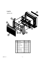
Page 17: ...ssy 3 Panel Front L 4 Panel Front R 6 Air Clean Filter Assy Parts number Description Ref 9316418011 9316458017 9316187016 9316186019 9312152018 Remote Control Holder 9305642045 Remote Control 9316397019 Bracket Panel 9 9316272019 8 Panel Front 9316185012 5 5 Air Filter 9316189010 ...

Page 18: ...e 20 Pipe Thermistor 21 Display Case 9302271002 9316307018 9316270015 9316193017 9900425012 9316194014 22 Display PCB Assy 9707571028 23 15 Bracket Terminal 9316269019 17 Parts number Description Ref Display Cover 9316191013 24 Thermistor Holder 9316192010 25 Room Thermistor 9700801108 32 Control Box 9316200012 31 Controller PCB Assy 09 32 Controller PCB Assy 12 32 Controller PCB Assy 14 970750507...

Page 19: ...vaporator Holder Evaporator Total Assy 09 12 37 Evaporator Total Assy 14 37 Water Seal Parts number Description Ref 9316199019 9316091016 9316271012 18 2008 01 21 37 9316091023 36 42 41 41 42 U Pipe AA Assy 9316095014 ...

Page 20: ...18 Casing 49 9316204010 Fan Guard 9316211018 19 2008 01 21 58 43 49 55 56 57 54 53 52 51 50 46 Bushing B 50 9312156016 Bushing A 51 9303529010 Motor Step up down 54 9900384043 Gear A 53 9309994003 Gear Case 52 9316213012 REF Casing 57 58 9316378018 Louver Z 56 9316206014 Louver U 55 9316205017 ...

Page 21: ...se Assy 65 9314147029 64 Drain Pan U 9316214019 20 2008 01 21 68 71 66 Motor Step Damper Lock Right 9900384074 Damper 70 9316216013 Bushing A 69 9303529010 Bushing B 68 9312156016 72 R and L Louver Z 71 9316334014 61 59 62 64 65 66 69 70 72 77 76 75 Drain Pan Assy 9316412019 Fan Guard Z 75 9316918009 Cover Lower 76 77 9316374010 Stopper 9316219014 Drain Pan Z 9316215016 ...

Page 22: ...y 3 Fan Guard 9 Propeller Fan Assy 10 Fan Motor 12 Base Assy 13 Cap Foot 14 Protective Net 9374417049 9374094080 9374415045 9374599042 9374827015 7 Grip 9374172016 9374330010 4 Grip Side 9374173013 9366378020 9601882015 11 Condencer A Assy 9374433179 9374166121 9374345014 9375381028 Emblem Rear 9351355005 Ref Description Part number 2008 01 21 ...

Page 23: ...75 Thermo Holder 76 Compressor Cover A 77 Compressor Cover B 78 Compressor Cover C 9375221058 9375222017 9375211011 9374430093 9374431090 9372067079 9900372019 17 Separate Wall Assy 18 Coil Choke 19 Compressor Assy 20 4 Way Valve Assy 21 Inlet Pipe Cond A Assy 22 Outlet Pipe Cond A Assy 23 Pressure Switch A 24 Pressure Switch B 25 Accumulator Assy 26 Receiver Tank Assy 27 Valve Plate A Assy 28 Pul...

Page 24: ...139018 9375138011 9374606023 51 Terminal 3P 9306489045 9900016036 0501454012 0501456016 0600086039 0600376116 9701971015 9703457012 9705647091 61 Controller PCB Assy 24LAT3 62 Holder Thermo 63 Heat Sink Thermistor 64 Compressor Temp Thermistor 65 Thermistor Outdoor Temp 66 Heat Exchanger Thermistor 67 Discharge Temp Thermistor 68 Wire Pressure Sw Red 69 Wire Pressure Sw White 9705642195 61 Control...

Page 25: ...316272019 9316397019 0600185527 9310519004 9305642045 0700076046 0700019036 Use for air conditioner operation For remote control For indoor unit installation Use as remote control holder For wall hook bracket and body installation For remote control unit holder installation Part number 3 x 12 4 x 25 24 2008 01 09 Electric filter UTR FC03 2 Ion deodrant filter UTR FC03 3 1 1 9312833009 9312832002 W...

Page 26: ...007 303020200114 Use Part number For outdoor unit drain piping work Q ty 1 2 Name and Shape Drain pipe Drain cap For use when connecting models 9 12 to outdoor port A For sealing 1 1 Adapter assy Putty 12 7 mm 9 52 mm 1 2 in 3 8 in 22 2007 12 28 ...

Page 27: ...0801G3351 ...

Reviews: