background image

OUTDOOR UNIT

2008.11.13

24

56

55

54

57

18

17

26

42

25

19

24

23

21

22

20

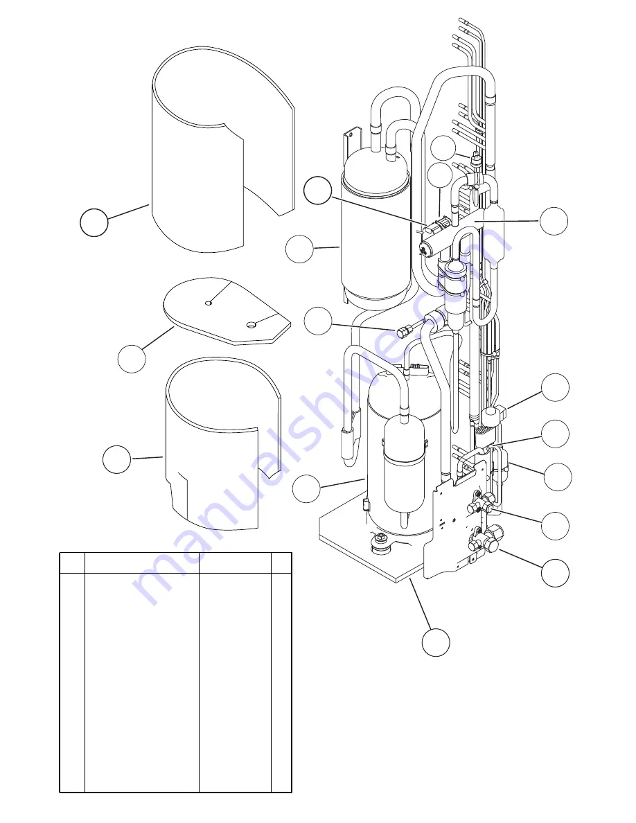
17 3-Way Valve Assy
18 3-Way Valve Assy
19 Compressor Assy
20 Accumulator Assy

21

Solenoid

22 Pressure Switch
23

4-Way Valve

24 Check Valve Assy
25 Coil (Expansion Valve)
26 Strainer Assy

55 Compressor Cover B
56

Compressor Cover C

57 Compressor Cover D

42 Expansion Valve Assy
54 Compressor Cover A

9377958013
9377959010
9378035010
9375250034
9900165055
9900186012

9970035029

9374274017
9900197025
9372524039

9374431106
9372067086
9375382025

9370947175
9374430109

Description

Parts number

Ref.

58 Solenoid

9900165055

58

Summary of Contents for ABYA45LCT

Page 1: ... Outdoor unit ABYA45LCT AOYA45LBTL CONTENTS SPECIFICATIONS 1 DIMENSIONS 2 REFRIGERANT SYSTEM DIAGRAM 4 CIRCUIT DIAGRAM 5 ERROR DETECTION 6 INDOOR PCB CIRCUIT DIAGRAM 10 OUTDOOR PCB CIRCUIT DIAGRAM 13 PARTS INDOOR UNIT 17 PARTS OUTDOOR UNIT 22 ACCESSORIES 26 ...

Page 2: ...kW kW 15 0 A 4 5 L hr 6 200 m3 h MAXIMUM CURRENT 20 0 A AIRCIRCULATION INDOOR 2 100 m3 h 6 900 m3 h MFH 45RV 1 200 r p m 1 000 r p m 830 r p m Quiet 680 r p m 12 5 kW 14 0 kW ELECTRICAL DATA TYPE DISCRIMINATION WEIGHT with oil REFRIGERANT TYPE R410A Hermetic type Inverter 4 poles 3 phase DC motor Twin Rotary PRECHARGED REFRIGERANT COMPRESSOR AND REFRIGERANT 2009 02 25 1 SPECIFICATIONS MAX PIPE LEN...

Page 3: ...DIMENSIONS 1 660 240 700 1 600 130 300 Unit mm INDOOR UNIT 2098 02 10 2 ...

Page 4: ... Unit mm OUTDOOR UNIT 2009 02 10 3 31 900 330 12 9 21 1 290 400 650 370 Air Flow 77 ...

Page 5: ...e 15 88mm 5 8 Cool Refrigerant direction Heat Evaporator Refrigerant Pipe 9 52mm 3 8 Charging Valve Charging Valve Accumulator Strainer Compressor Expansion Valve Strainer Condenser Strainer 4 way Valve Muffler x 2 Pressure Check Valve High Pressure Switch 2009 02 10 4 ...

Page 6: ...PTION PART POWER SUPPLY PCB ASSY CONTROLLER PCB ASSY WHITE WHITE YELLOW BROWN WHITE BLACK RED YELLOW BROWN WHITE BLACK RED YELLOW BROWN WHITE BLACK RED BLUE ORANGE WHITE BLACK BROWN RED BLACK BLACK WHITE WHITE GREEN BLACK WHITE ORANGE ORANGE RED BLACK BLUE YELLOW YELLOW ORANGE RED BROWN BLACK WHITE RED BLACK BLACK BROWN BLACK BROWN BLUE BLACK BLACK RED RED BROWN WHITE 1 2 3 4 5 6 1 2 3 4 5 6 1 2 3...

Page 7: ...PCB Circuit Diagrams not available at time of publication ...

Page 8: ... sensor middle error 3 times 5 times Heat sink thermistor P F C error 4 times 2 times Indoor manual auto switch abnormal 4 times 4 times Power supply frequency detection error 5 times 2 times IPM protection 5 times 3 times CT error 5 times 5 times Compressor location error 5 times 6 times Outdoor fan error 5 times 7 times Connected indoor unit abnormal 5 times 8 times Outdoor unit computer communi...

Page 9: ... sensor outlet error 0A Outdoor temperature sensor error 0E Heat sink thermistor Inverter error 15 Compressor temperature sensor error 1d 2 way valve temperature sensor error 1E 3 way valve temperature sensor error 29 Outdoor heat exchanger temperature sensor middle error 2d Heat sink thermistor P F C error 20 Indoor manual auto switch abnormal 2A Power supply frequency detection error 17 IPM prot...

Page 10: ...er temperature outlet sensor Outdoor heat exchanger temperature mid sensor Outdoor temperature sensor Compressor temperature sensor Heat sink temperature sensor Pressure switch abnormal IPM error Compressor rotor position cannot detect Compressor cannot operate Outdoor fan abnormal upper fan Outdoor fan abnormal lower fan Pump down operation No error LED 1 flash 2 flash 3 flash 4 flash 5 flash Dis...

Page 11: ...on starts After 2 3 minutes operation stops Close the three way valve gas within one minute after operations stops The LED will go out three minutes after it stops Dis connect the power supply after confirming that the LED has gone out 3 way valve Liquid 3 way valve Gas DANGER This part Choke coil generates high voltages Never touch this part PUMP DOWN SW SW2 20 to 25 N m 200 to 250 kgf cm 20 to 2...

Page 12: ...9691006 20 Badge 9359735083 14 Hinge Plate Grille 9359694007 7 Filter Guide R 9359692003 8 Filter Guide L 9359693000 16 Cover Decoration R 9359744009 17 Cover Decoration L 9359745006 10 Indicator PCB Assy 9705891043 2 Panel Left Sub Assy 9360427014 3 Kit Panel Right Assy 9371361017 4 Cover Top 9359737001 18 Kit Side Cover R 9371364018 19 Kit Side Cover L 9371365015 12 Receiver Cover 9359714002 11 ...

Page 13: ...3011 28 Flap Assy 9359731009 29 Bushing 9359733003 Drain Cap 9358746004 23 Coupling Pipe Assy 9373038405 2 Panel Left Sub Assy 9360427014 3 Kit Panel Right Assy 9371361017 26 Reinforcement Metal 9359697008 31 Sector Gear 9359729006 30 Flap Spring 9359730002 32 Pinion Gear 9359728009 33 Motor Base 9359727002 22 Distributor Assy 9371325378 36 Pipe Fixture Metal 9359688006 Thermistor Spring A 3137282...

Page 14: ...ver Base Sub Assy 9360432025 43 Rod Motor 9359723004 44 Louver Link 9359726005 45 Louver Base 9359718000 46 Louver Spring 9359720003 47 Louver Stopper 9359724001 48 Louver Rod 9359725008 49 Step Motor H 9900297015 50 Louver Insulation R 9359721000 51 Louver Insulation L 9359722007 Ref Description Part number ...

Page 15: ...y 9357921006 61 Motor Mount 9377999016 62 Fan Motor Assy 9602389018 63 Motor Band A assy 9374647019 64 Motor Band B 9374648023 65 Reinforcement Motor Band 9378000018 66 Rubber 9385102002 72 Shaft Holder Bracket 9359686002 71 Shaft 9359707004 70 Joint Assy 9378038011 74 Shaft Holder Fixture 9359687009 68 Kit Cover Casing Sub Assy 9371367019 Ref Description Part number ...

Page 16: ...9707393453 94 Wire Assy Connector 9707442021 95 Wire Assy Connector 9703339028 96 Wire Assy Connector 9702319014 97 Wire Assy Connector 9702318017 98 Remote Control 9315885012 99 Remote Control Holder 9305642045 83 Control Box B 9359713005 82 Control Box A 9359712008 86 Terminal 3P 9703345012 87 Terminal 3P 9306489045 88 Reactor Assy 9707457018 85 Power Supply PCB Assy 9707398168 91 Cord Clamp A 9...

Page 17: ... 1 Top Panel Sub Assy 2 Front Panel 3 Fan Guard 4 Grip Side 5 Service Panel Sub Assy 6 Right Panel Sub Assy 7 Valve Cover 9374417025 9374094028 9374330010 9374173013 9374415069 9374416141 9374174010 Emblem Rear 9351355005 Description Parts number Ref ...

Page 18: ... 23 9 Propeller Fan Assy 10 Motor DC Brushless 11 Condenser A Assy 12 Condenser B Assy 13 Separate Wall 14 Cap Foot 15 Base Assy 9366378020 9602843015 9374433018 9374434015 9374629015 9374345014 9374166046 Description Parts number Ref 16 16 Coil Choke 9703458019 ...

Page 19: ...ve 24 Check Valve Assy 25 Coil Expansion Valve 26 Strainer Assy 55 Compressor Cover B 56 Compressor Cover C 57 Compressor Cover D 42 Expansion Valve Assy 54 Compressor Cover A 9377958013 9377959010 9378035010 9375250034 9900165055 9900186012 9970035029 9374274017 9900197025 9372524039 9374431106 9372067086 9375382025 9370947175 9374430109 Description Parts number Ref 58 Solenoid 9900165055 58 ...

Page 20: ... Box A 28 Inverter Box B 29 Inverter Box C 30 Inverter Box Duct 36 Posistor 38 Power PCB Assy 39 Clamp Cord 40 Terminal 41 Fuse Small 43 Thermistor Dischage 44 Thermistor Heat Exchanger 45 Thermistor Outdoor 46 Compressor Thermistor 31 Inverter Box Cover 32 Heat Sink B 33 ACTPM 9374603015 9374625017 9374605026 9374609017 9704265012 37 Inverter PCB Assy 9708013183 9705647022 9356857009 9900203023 0...

Page 21: ... For installing indoor unit 1 312300787605 9360464002 313806350303 9378173569 9374714025 9378173521 9301501001 313005446653 313005446759 9360022004 For connecting the piping 1 Auxiliary pipe assembly ACCESSORIES 2009 02 25 26 0700019036 0600185541 9305642045 9315885012 1 1 2 2 For air conditioner operation For installing remote control on the wall For remote control For mounting the remote control...

Page 22: ...Exterior 2009 02 25 27 Parts name Model No Summary Wired remote control UTB YUD UT UT Unit control is performed by wired remote control Round duct UTD RF204 For Ceiling type Drain pump unit UTR DPB241 For Ceiling type ...

Page 23: ...0902G3600 ...

Reviews: