background image

Cleaning the server

Preparation for use and operation

A26361-K646-Z102-1-7619

31

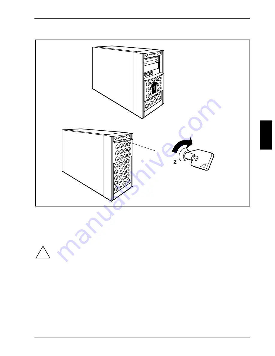
Locking the server

Ê 

Slide the drive cover upwards (1).

Ê 

Lock the server (2).

4.6

Cleaning the server

!

Switch the server off and pull the power plug out of the grounded-contact power socket.

Do not clean any interior parts yourself, leave this job to a service technician.

Do not use any cleaning agents that contain abrasives or may corrode plastic.

Ensure that no liquid enters the system.

Ensure that the ventilation areas of the server and the monitor are free.

Wipe the server and monitor casing with a dry cloth. If particularly dirty, use a cloth which has been
moistened in mild domestic detergent and then carefully wrung out.

Use disinfectant wipes to clean the keyboard and the mouse.

Summary of Contents for PRIMERGY B120

Page 1: ...SERVER SERVER SERVER SERVER PRIMERGY B120 PRIMERGY B120 PRIMERGY B120 PRIMERGY B120 Intel based Server Systems OPERATING MANUAL OPERATING MANUAL OPERATING MANUAL OPERATING MANUAL ...

Page 2: ...ntact one of our service partners your sales partner your sales outlet Further information can be found in the guarantee booklet or in the service address booklet The latest information on our products tips updates etc can be found on the Internet under http www fujitsu siemens com ...

Page 3: ......

Page 4: ...to manuale è stato stampato su carta da riciclaggio Denna handbok är tryckt på recyclingpapper Dit handboek werd op recycling papier gedrukt Herausgegeben von Published by Fujitsu Siemens Computers GmbH Bestell Nr Order No A26361 K646 Z102 1 7619 A26361 K646 Z102 1 7619 A26361 K646 Z102 1 7619 A26361 K646 Z102 1 7619 Printed in the Federal Republic of Germany AG 0201 02 01 A26361 K646 Z102 1 7619 ...

Page 5: ...l Introduction Important notes Installation P i f d Preparation for use and operation Opening and closing the server Property and data protection Troubleshooting and tips System components and expansions Index February 2001 edition ...

Page 6: ...demarks of their respective owners whose protected rights are acknowledged Copyright ã Fujitsu Siemens Computers GmbH 2001 All rights including rights of translation reproduction by printing copying or similar methods even of parts are reserved Offenders will be liable for damages All rights including rights created by patent grant or registration of a utility model or design are reserved Delivery...

Page 7: ... 3 7 Connecting devices to the server 21 4 Preparation for use and operation 23 4 1 Unlocking locking the tower server 23 4 2 Operation controls 25 4 2 1 Operation controls 26 4 2 2 Indicators 26 4 2 3 Drive indicators 26 4 3 Switching the server on and off 27 4 4 Configuring the server 29 4 4 1 Configuration with ServerStart 29 4 4 2 Configuration without ServerStart 29 4 4 3 Installing the opera...

Page 8: ...placement of SCSI hard disk drive during operation 45 8 1 3 Installing removing a SCSI hard disk drive 46 8 1 4 SCSI platter for four 1 inch hard disk slide in modules 47 8 2 Accessible drives 48 8 2 1 Installing Removing an accessible 5 inch drive 49 8 2 2 Changing the floppy disk drive 50 8 3 Removing installing boards 51 8 4 chipDISK for RemoteView 52 8 4 1 Installing removing the chipDISK 52 8...

Page 9: ...ntee and Ergonomics in the Technical Manual of the system board with the description for the BIOS setup in the technical manual for the rack rack server in the manual for the monitor in the manual for the ServerView server management in the manual for the Remote Test and Diagnosis System RemoteView in the documentation for the boards and drives in the documentation of your operating system in the ...

Page 10: ...k via a central console In the process ServerView supports the following functions depending on the system board of the server Remote power on Wakeup On LAN Intrusion Detection Temperature monitoring of the CPU and the surrounding area Power monitoring End of Life monitoring of the fans with timely indication before failure Watchdog timer for operating system and applications with Automatic Server...

Page 11: ...ds or menu items Quotation marks indicate names of chapters and terms that are being emphasized 1 3 Technical data Electrical data standard power supply Rated voltage range selectable 100 V 125 V 200 V 240 V Frequency 50 Hz 60 Hz Rated current in basic configuration Server without monitor outlet or with an unused monitor outlet 100 V 125 V 1 3 A 200 V 240 V 0 7 A Max rated current Server without m...

Page 12: ... Compatibility 89 336 EEC Product safety Mechanical data Dimensions W x H x D 428 x 204 x 460 mm rack mounting 5 height units HU Weight approx 14 24 kg depending on the configuration Ventilation gaps DIN IEC 721 part 3 3 Environmental conditions Environment class 3K2 Environment class 2K2 DIN IEC 721 part 3 3 DIN IEC 721 part 3 2 Temperature Operating 3K2 Transport 2K2 15 C 35 C 25 C 60 C Condensa...

Page 13: ...e may be caused to the device if this requirement is not observed Installation and operation WARNING The server automatically sets itself to a line voltage in the range of 100 V to 240 V Ensure that the local mains voltage lies within these limits This device has a safety tested power cable and must only be connected to a properly grounded wall outlet Ensure that the power socket on the device or ...

Page 14: ... personnel The warranty is invalidated if the device is damaged during the installation or replacement of system expansions You may set only those resolutions and refresh rates specified in the Technical data section of the monitor description Otherwise you may damage your monitor If you are in any doubt contact your sales outlet or customer service center Batteries WARNING Incorrect replacement o...

Page 15: ...ing or pulling out boards containing ESDs Always hold boards with ESDs by their edges Never touch pins or conductors on boards fitted with ESDs Other important notes When cleaning the device please observe the relevant notes in the paragraph Cleaning the server Keep this Operating Manual safety and all additional documentation e g Technical Manual CD in a safe place together with the device If you...

Page 16: ...determined by turning the equipment off and on the user is encouraged to try to correct the interference by one or more of the following measures Reorient or relocate the receiving antenna Increase the separation between equipment and the receiver Connect the equipment into an outlet on a circuit different from that to which the receiver is connected Consult the dealer or an experienced radio TV t...

Page 17: ...stem unit and the devices should only be transported in their original packaging Note on dealing with consumables Please dispose of printer consumables and batteries in accordance with local government regulations Do not throw lithium batteries or accumulators into the trashcan They must be disposed of in accordance with local regulations concerning special waste Note on labeling plastic casing pa...

Page 18: ......

Page 19: ...ting the rack version refer to the information in section Installing rack server in removing from rack Ê Connect the server to the power supply see section Connecting the tower server to the line voltage and Connecting the rack server to the line voltage 3 2 Unpacking the server Please take note of the safety information in the chapter Technical data Do not unpack the server until all transportati...

Page 20: ...Plug all data communication cables into the utility sockets Plug all power cables into the grounded power outlets Disconnecting cables Turn off all power and equipment switches Pull all power plugs out of the grounded power outlets Unplug all data communication cables from the utility sockets Disconnect the relevant cables at the server and at the peripherals 3 4 Setting up the tower server If you...

Page 21: ... one of the standard power supplies Both designs for the standard power supply can be set for supply voltage ranges 100 V to 125 V or 200 V to 240 V Before connecting the server to the line voltage you must always check that the line voltage range set on the server corresponds to the local line voltage The marker arrow on the plug in unit points to the voltage range set 100 V 125 V 200 V 240 V a Ê...

Page 22: ...so given on the monitor itself or in the Operating Manual for the monitor 3 5 Installing rack server in removing from rack Please observe the safety precautions and references to rack installation in the chapter Important notes as well as the mounting instructions in the technical manual for the corresponding rack i The server may not occupy the top height unit of the 19 inch rack as otherwise no ...

Page 23: ...26361 K646 Z102 1 7619 15 3 5 1 Mounting the slide in module 1 2 Ê Screw together the front panel and the bottom tray to form a slide in module 1 2 Ê Place the server in the slide in module with the right side facing downward and somewhat offset toward the rear ...

Page 24: ...ation Installing rack server in removing from rack 16 A26361 K646 Z102 1 7619 Ê Push the server up to the front panel 2 1 Ê Secure the server at the back to the bottom tray with the angled mounting bracket 1 2 ...

Page 25: ... rails are mounted in the bottom height unit One height unit is equal to 4 445 cm 1 inches Fitting spring nuts 2 3 ca 45 4 5 5 1 Ê Insert the spring nuts in the corresponding groove of the support upright at the mounting points for the sliding rails and the server 1 4 Ê If necessary adjust the position of the nuts in the groove until they lock into the correct position 5 ...

Page 26: ...on in the corresponding mounting hole as shown in the illustration 1 Ê Then pry and pull the upper section of the cage nut into the mounting hole with the tool supplied 2 The cage nut should be engaged in the mounting hole as shown in 3 Ê Screw on the sliding rails at the left and right in the rack with an Allen key The left and right sliding rails are identical ...

Page 27: ... that the connection panel is rotated 180 Since the connection panels are otherwise identical the diagrams below show only one of the standard power supplies The power supply of the server can be set to the following line voltage range 100 V to 125 V or 200 V to 240 V Before connecting the server to the line voltage you must always check that the line voltage range set on the server corresponds to...

Page 28: ...d into a free electrical outlet of the multi outlet assembly in the rack 2 see technical manual for rack Guide the cable through the cable routings of the rack 3 6 Prepare the keyboard Ê Plug the appropriate connector of the keyboard cable into the socket on the underside of the keyboard as shown in the illustration above ...

Page 29: ...rts are marked with symbols and some are color coded 7 6 3 4 5 2 1 Tower 7 6 3 4 5 2 1 Rack 1 Mouse 2 Parallel interface burgundy 3 LAN 4 Monitor blue 5 Serial interface 1 teal or turquoise 6 USB black 7 Keyboard violet Ê Connect the data cables at the server and peripherals i Some of the devices that you connect require special drivers see the documentation for the connected device Ê Mark the lin...

Page 30: ... power supply then the current consumption of the monitor may not exceed 1 5 A at 230 V or 3 A at 115 V The rated current for the monitor is also given on the monitor itself or in the Operating Manual for the monitor When connected to an uninterruptible power supply UPS the monitor must also be taken into account Guide the cables through the cable routings of the rack ...

Page 31: ... the tower version For details on the rack variant please see the Technical Manual for the rack 4 1 Unlocking locking the tower server Enabling access to the accessible drives 3 1 2 Ê Unlock the server 1 Ê Slide the drive cover downwards 2 Ê If you wish to prevent access to the hard disk drives then lock the server again 3 Now the drive cover cannot be pushed into the top position and the hard dis...

Page 32: ...4 A26361 K646 Z102 1 7619 Enabling access to the hard disk drives 4 3 2 1 Ê Unlock the server 1 Ê Slide up the drive cover as far as possible 2 Ê Remove the hard disk cover toward the front 3 4 The hard disk cover is remounted and the server connected in the reverse order ...

Page 33: ...1 3 8 9 7 4 6 5 2 1 3 9 8 1 Floppy disk drive with power on indicator 2 CD ROM drive with power on indicator 3 Lock 4 Chipcard reader with power on indicator optional 5 IDE busy indicator 6 Message indicator 7 ON OFF switch with power on indicator 8 Hard disk indicator optional 9 Hard disk error indicator optional ...

Page 34: ... IDE busy indicator lights green when an IDE drive is being accessed 4 2 3 Drive indicators Hard disk indicator Lights when the hard disk drive in this slot is being accessed Hard disk error only in conjunction with disk array controller lights when the hard disk drive in this slot is defective and needs replacing It is possible that the drive is not correctly inserted flashes when a rebuild is ca...

Page 35: ...e server there is nothing but flickering stripes on the screen switch the server off immediately see Troubleshooting and tips Flickering stripes on the monitor screen The ON OFF switch and the main switch do not disconnect the server from the line voltage To disconnect the line voltage completely remove the power plug from the socket 0 I c a a c 0 I b b ...

Page 36: ...s live Server is switched on The main switch a is in position I and the power on indicator c does not light up The server can be made ready for operation with the ON OFF switch b or a signal The screen socket on the server is live Other switch on methods In addition to the ON OFF switch the server can be switched on in the following ways Specified switch on time switch off time The server is switc...

Page 37: ...driver diskettes To find out how to operate ServerStart and for further information see the corresponding CD booklet If you use ServerStart you can skip the following sections on how to configure the server and install the operating system Continue with the section Locking the tower server instead 4 4 2 Configuration without ServerStart Configuring the Disk Array Controller If your server is fitte...

Page 38: ...r server 30 A26361 K646 Z102 1 7619 4 5 Locking the tower server Fitting the hard disk cover 2 3 4 5 1 Ê If the server is locked unlock it 1 Ê Slide the drive cover completely upwards 2 Ê Fit the hard disk cover 3 4 Ê Slide the drive cover downwards 5 ...

Page 39: ...ny interior parts yourself leave this job to a service technician Do not use any cleaning agents that contain abrasives or may corrode plastic Ensure that no liquid enters the system Ensure that the ventilation areas of the server and the monitor are free Wipe the server and monitor casing with a dry cloth If particularly dirty use a cloth which has been moistened in mild domestic detergent and th...

Page 40: ......

Page 41: ... server off Pull the power plug out of the power outlet Ê Disconnect all cables on the rear that are obstructing you 5 1 Opening and closing the tower server 1 4 2 3 Ê Unlock the server 1 Ê Unscrew the two knurled screws 2 Ê Push the side cover approx 2 cm backwards 3 Ê Remove the side cover sidewards 4 Ê Closing is performed in the reverse order ...

Page 42: ...6361 K646 Z102 1 7619 5 2 Opening and closing the rack server 2 1 Ê Release the four knurled screws 1 and pull the server carefully out of the rack up to the stop 2 1 2 Ê Press the locking springs on both sides of the server 1 and carefully remove the server from the rack 2 ...

Page 43: ...ing and closing the server A26361 K646 Z102 1 7619 35 4 3 2 1 Ê Unlock the server 1 Ê Unscrew the two knurled screws 2 Ê Push the top cover approx 2 cm backwards 3 Ê Lift off the top cover upwards 4 Ê Closing is performed in the reverse order ...

Page 44: ......

Page 45: ...gram recognizes and logs any removal of the housing side cover and the hard disk cover To prevent the tower server from being stolen it can be secured to a fixed object with a steel cable run through the tab on the back The rack server is protected against unauthorized access with the lockable rack door For protecting your system and your data internally from unauthorized access you can use the BI...

Page 46: ......

Page 47: ... your customer service center 7 1 Operation indicator remains dark Power cord incorrectly connected Ê Make sure that the power cable is correctly connected to the server and to the grounded power outlet Power supply overloaded Ê Pull the power plug of the server out of the power outlet Ê Wait a few seconds and plug the power plug into the power outlet again Ê Switch your server on 7 2 The server s...

Page 48: ...he set horizontal frequency Ê Find out which horizontal frequency your monitor screen supports You will find the horizontal frequency also known as line frequency or horizontal deflection frequency in the documentation of your monitor Ê Refer to the documentation for your operating system or the corresponding driver software for the screen controller for how to set the correct horizontal frequency...

Page 49: ...p check the entry for the floppy disk drive Ê Check in the BIOS Setup whether the diskette drive controller and write permission are enabled see the Technical Manual for the system board Ê Check that the cables of the floppy disk drive are properly connected refer to chapter System components and expansions 7 8 Time and or date is not correct Ê Set the time and or date in the operating system or i...

Page 50: ... disk array controller 7 11 Added drive defective An added SCSI drive is reported as defective This error message may occur when the server has a disk array controller Disk Array Controller is not configured for this hard disk drive The drive was probably installed with the system switched off Ê Reconfigure the disk array controller for the hard disk drive Information is contained in the documenta...

Page 51: ...an be replaced during operation hot replace When an SCSI hard disk drive is operated in a hot replace capable SCSI subsystem on a disk array controller and is part of a disk array which operates in RAID Level 1 or 5 then it can be replaced in the case of a defect during operation hot replace To swap a hard disk you need an SCSI hard disk drive with the same or higher capacity You will identify a d...

Page 52: ...ctive hard disk and the data of the defective disk is rebuilt on the standby disk Ê Read the documentation for the new hard disk drive 8 1 1 SCSI hard disk drives The SCSI hard disks which can be ordered for the server are supplied already mounted in the hard disk carriers The slide in modules are equipped with a status and an error indicator Unequipped installation bays are covered with a blank i...

Page 53: ...8 1 2 Replacement of SCSI hard disk drive during operation Never pull out a hard disk during operation if you are not sure that the hard disk is operated on a disk array controller and is part of a disk array that operated in the mode RAID Level 1 or 5 Only if the orange indicator on the hard disk carrier remains bright may the hard disk be replaced while the system is in operation If you replace ...

Page 54: ...nism 1 and pull the blank insert out of the installation by 2 by the handle The blank insert is installed in the reverse order Keep the blank insert for future use If the hard disk drive is removed again and not replaced with a new drive then the blank insert must be reinstalled due to cooling the applicable EMC regulations regulations on electromagnetic compatibility and fire protection 2 1 Ê Pus...

Page 55: ...60 SCSI SCSI ID 3 SCSI ID 1 SCSI ID 0 SCSI ID 2 1 4 2 3 1 SCSI input SCSI controller 2 Power supply 3 Drive indicators 4 SCA ports hard disk carriers Each hard disk carrier is assigned to two drive indicators The upper indicator green shows the drive activity The lower indicator orange shows a hard disk error However a hard disk error can only be indicated when the drive is operated on a disk arra...

Page 56: ...n one drive must be set as the master and the other as the slave Only drives with the same speed should be connected to an IDE channel SCSI drive The drive must be assigned a unique SCSI ID With narrow SCSI drives an SCSI ID from 0 to 6 and with wide SCSI drives also from 8 to 15 can be assigned The drive terminating resistor must be switched on or off in accordance with the following consideratio...

Page 57: ...completely disconnect the device from the network remove the power plug from the line voltage Ê Open the server see Opening and closing the server 1 2 3 Ê Disconnect the cables from the drive 1 Ê Remove the two fastening screws 2 and take out the drive toward the front 3 The new drive is mounted in reverse order If you do not install a new drive proceed as follows 1 a 2 b Ê Mount an EMC insert a a...

Page 58: ...letely disconnect the device from the network remove the power plug from the line voltage Ê Open the server see Opening and closing the server 1 2 3 Ê Disconnect the cables from the floppy disk drive 1 Ê Remove the fastening screw 2 and withdraw the floppy disk drive from the bay 3 Ê Push the new floppy disk drive into the bay and secure it with the screw you removed earlier Ê Connect the cables t...

Page 59: ... line voltage Ê Remove the cables from the board 1 2 a Ê Remove the fastening screw 1 and take out the board of the slot 2 If no board was installed remove the rear slot cover plate Do not dispose of the rear slot cover plate For cooling protection against fire and in order to comply with EMC regulations you must refit the rear slot cover plate if you remove the board Ê Insert the board in the req...

Page 60: ...K Ê Exit the operating system switch off the server and disconnect it from the power supply Switching off the server does not disconnect the device from the network To completely disconnect the device from the network remove the power plug from the line voltage Ê Open the server and remove the side cover and the slot cover see the chapter Opening and closing the server 3 2 MSC 1 Ê Connect the plug...

Page 61: ...emoteView to be started automatically later Proceed as follows Ê Reboot the server Ê Press the function key F2 F2 F2 F2 if the message Press F2 to enter Setup is displayed on the screen Ê In the BIOS Setup select the menu item IDE Drive 1 from the Main monitor page Ê Set the value for Type to Auto Ê Select the Server menu in the BIOS setup Ê Set the value for Diagnostic System to enabled Change th...

Page 62: ... see Opening and closing the server 1 3 2 a Ê Pull the cable off the fan 1 Ê Press on the clip 2 from behind and remove the fan 3 Ê Place the new fan in the bay The proper fan position can best be judged from the outside at the back of the server When doing so make sure the fan clip a engages properly 2 Ê Connect the cable to the fan Ê Close the server again see Opening and closing the server ...

Page 63: ... fan control this setting must not be changed 2 Fan control connector 3 System fan connector 4 Power supply connector 5 I2 C connector 6 Controller 8 7 System board Details of how you upgrade the main memory of the server replace the lithium battery or processor or make certain settings are provided in the Technical Manual of the system board Ê Open the server see Opening and closing the server Ê ...

Page 64: ......

Page 65: ...t 41 Defective drive 42 Device ID 55 Devices connecting 21 Diagnostic system 52 Dimensions 4 DIP switch 55 Disk Array Controller 1 29 43 47 configuring 29 defective drive 42 Display cleaning 31 Disposal and recycling 9 Drive changing floppy disk drive 50 installing accessible 5 inch drive 49 removing accessible 5 inch drive 49 reported as dead 42 SCSI hard disk drive 43 Drive cover 23 Drive indica...

Page 66: ...disk drive 26 hard disk drive 26 IDE busy 26 operation 26 Indicators 25 Information general 1 Installation 11 Installation and operation 5 Installing hard disk cover 30 rack server 14 Interfaces 21 Italics 3 K Keyboard cleaning 31 connecting 20 Keyboard port 21 L Label on plastic casing parts 9 LAN port 21 Light emitting diode 6 Line voltage connecting rack server 19 connecting tower server 13 Lin...

Page 67: ...48 SCSI platter hot replace 47 SCSI hard disk subsystem 43 SCSI platter 4 x 1 inch carriers 47 SCSI ID hard disk drive 29 43 SCU 29 Security measures 37 Security standards 4 Serial port 21 Server opening 33 switches itself off 39 Server management 2 ServerStart 2 29 ServerView 2 Setting up tower server 12 Side cover removing 33 Slide in module installing 17 mounting 15 Spring nut fitting 17 Standa...

Page 68: ...ouse pointer 41 screen 39 screen display drifts 40 server 39 server switches itself off 39 system does not boot 41 Troubleshooting and tips 39 U U160 SCSI 47 Ultra160 SCSI 43 Ultra3 Wide SCSI 47 Unlocking tower server 23 USB port 21 V Ventilation gaps 4 W Wakeup On LAN WOL 28 Warranty features 6 Weight 4 Winter time 41 Wrong date 41 Wrong time 41 ...

Reviews: