background image

16

Basic Operation

On/Standby

 Turning the Projector On

 Turning the Projector On

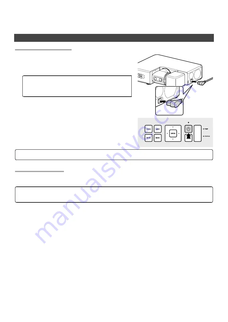
Connect the supplied power cable to the projector and plug it 
into a power outlet.

The projector will switch to standby mode.

4

 CAUTION

The supplied power cable is for use exclusively 
with FP-Z5000 projectors. Do not use it with 
any other product.

Press the power button to turn the projector on.

4

 CAUTION

Do not look directly into the lens while the projector is on. 

Switching to Standby

Switching to Standby

Pressing the power button while the projector is on displays a confi rmation dialog.  Press the button again to 
switch the projector to standby. The cooling fan will turn off  a few seconds later.

4

 CAUTION

The lens latches cannot be released while the projector is on standby; check the position of the lens 

and replace the lens cap before switching the projector to standby.

Summary of Contents for FP-Z5000

Page 1: ...Projector Basic Manual Installation and Basic Operation BL00005017 202...

Page 2: ...t the Icons 6 Disposal of Electrical and Electronic Equipment in Private Households In the European Union Norway Iceland and Liechtenstein 6 Introduction 7 Package Contents 7 Parts of the Projector 8...

Page 3: ...rs 23 Technical Notes 24 Supported Resolutions 24 HDMI HDBaseT 24 The Remote Control 25 Indicator Lamps 26 Regulatory 27 Safety 27 Laser Safety 27 Electro Magnetic Compatibility 27 Emissions 27 Immuni...

Page 4: ...could result in electric shock Do not modify tug or twist the connecting cables subject them to excessive heat or place them under heavy objects Damage to the cables could result in fire or electric...

Page 5: ...t leave the product in locations where it will be exposed to high temperatures or direct sunlight Fail ure to observe this precaution could result in fire Do not leave the product or if the batteries...

Page 6: ...t install the product in locations subject to shock or vibration Do not touch the lens immediately after switching the product to standby Failure to observe this precau tion could result in burns Be s...

Page 7: ...which has the following characteristics The light source may dim under certain conditions The higher the temperature the more the source will dim The source will grow dimmer the longer it is used The...

Page 8: ...equired to correct the interference at his own expense FCC Warning FCC Warning To assure continued compliance follow the attached installation instructions This includes using the pro vided power cord...

Page 9: ...eland and Liechtenstein Union Norway Iceland and Liechtenstein This symbol on the product or in the manual and in the warranty and or on its packaging indicates that this product shall not be treated...

Page 10: ...Remote control with two AAA batteries Lens cap HDMI cable approximately 1 8 m 5 9 ft Power cable approximately 3 m 9 8 ft Stand 2 BL00005017 100 Projector Basic Manual Installation and Basic Operatio...

Page 11: ...ure warning lamp J Remote receivers 25 K Screw holes for attaching stands 10 Item Name See page L Interface connector panel 23 M Model number plate laser warning sticker 4 N Speaker O Security slot P...

Page 12: ...40cm 1 3 ft Exhaust 40cm 1 3 ft 40cm 40cm When installing two or more projectors side by side leave a space of at least 80 cm 2 6 ft between them You will also need to ensure that the warm air from t...

Page 13: ...ing their built in screws which screw into the attachment holes on the projector When attaching the stands lay the projector flat The lens should be in the storage position the projector in standby mo...

Page 14: ...nce are available via a simulator on the Fujifilm website https optics fujifilm com projector en spec A Projection distance cm in minimum projector zoomed all the way out to maximum projector zoomed a...

Page 15: ...50 4 to 12 2 90 194 109 76 4 42 9 72 80 28 3 31 5 144 to 35 56 7 to 13 8 100 215 121 84 6 47 6 81 89 31 9 35 0 160 to 39 63 0 to 15 4 120 258 145 101 6 57 1 97 107 38 2 42 1 192 to 47 75 6 to 18 5 15...

Page 16: ...Fujifilm website https optics fujifilm com projector en spec A Projection distance cm in minimum projector zoomed all the way out to maximum projector zoomed all the way in B Vertical distance from ce...

Page 17: ...53 to 19 60 2 to 7 5 90 109 194 42 9 76 4 72 80 28 3 31 5 172 to 22 67 7 to 8 7 100 121 215 47 6 84 6 81 89 31 9 35 0 191 to 24 75 2 to 9 4 120 145 258 57 1 101 6 97 107 38 2 42 1 230 to 29 90 6 to 11...

Page 18: ...C Selector e f g h Navigate the menus D ENTER Select the highlighted menu item E Power Turn the projector on or switch it to standby F Arm latch release Unlatch the rotating arm G Head latch release...

Page 19: ...Press the power button to turn the projector on 4CAUTION Do not look directly into the lens while the projector is on Switching to Standby Switching to Standby Pressing the power button while the proj...

Page 20: ...nually re engaged within 10 seconds The LED lights when the head latch release is pressed RotatingtheArm RotatingtheArm When the arm latch is disengaged by pressing the arm latch re lease the arm can...

Page 21: ...be visible depending on lens shift and the orien tation of the lens When rotating the lens keep it supported and rotate it slowly To protect the lens the arm locks to prevent it rotating in the direct...

Page 22: ...s of the projected image can be adjusted by focusing the projector ABC 1 Press the LENS button until focus settings are displayed 2 Adjust focus using the selector e f g h 3 Press BACK to exit bTIP Fo...

Page 23: ...the LENS button until lens shift settings are displayed 2 Positiontheprojectedimageusingtheselector e f g h 3 Press BACK to exit bTIPS The selected shift position is stored when the lens is rotated Th...

Page 24: ...projected image can be adjusted using zoom ABC ABC 1 Press the LENS button until zoom settings are displayed 2 Adjust the size of the projected image using the selector e f g h 3 Press BACK to exit bT...

Page 25: ...lel with the edges of the screen can be corrected using keystone compensation ABC ABC 1 Press the MENU button to display the menus 2 Highlight Keystone using the selector e f and press ENTER to displa...

Page 26: ...hird Party Video Transmitters Third party video transmitters that support HDBaseT can be connected via the projector s HDBaseT LAN RJ45 connector 4CAUTIONS Use an STP LAN cable with category 5e shield...

Page 27: ...HDMI HDBaseT Signal Resolution pixels Refresh rate Hz VGA 640 480 60 SVGA 800 600 XGA 1024 768 WXGA 1280 768 1280 800 1366 768 SXGA 1280 960 1280 1024 SXGA 1400 1050 WXGA 1440 900 WSXGA 1680 1050 UXGA...

Page 28: ...CORNER FIT Display corner t options N Remote control lock Disable the remote control Be sure to aim the remote at the remote receiver when performing this operation O PICTURE Adjust settings for the...

Page 29: ...or status Power TEMP STATUS On amber O O Projector in standby mode On white O O Projector on On white Flashing amber O Projector temperature elevated On white On amber O Laser temperature elevated O O...

Page 30: ...electronic equipment and the applicable official amendment s EU Regulation EC No 1907 2006 on the registration evaluation authorization and restriction of chem icals REACH and the applicable official...

Page 31: ...wer cord is required in order to meet FCC emission limits and also to prevent interference to the nearby radio and television reception It is essential that only the supplied power cord be used Use on...

Page 32: ......

Reviews: