E R R O R D I S P L A Y
1flash
2 flash
3 flash
4 flash
7 flash
8 flash
9 flash
12 flash
13 flash
14 flash
Communication error
(Indoor unit Outdoor unit)
Discharge pipe temperature sensor
Outdoor heat exchanger temperature sensor
Outdoor temperature sensor
Compressor temperature sensor
Heatsink temperature sensor
Pressure switch abnormal
IPM error
Compressor rotor position cannot detect
Compressor cannot operate
15 flash
Outdoor fan abnormal (upper fan)
16 flash
5 sec. ON/
1 sec. OFF
repeated
Outdoor fan abnormal (lower fan)
Protect operation
No error
lighting
CAUTION
Supply power to the crankcase heater for at least 12
hours before the start of operation in winter.
(1) Stop the air conditioner operation.
(2) Press the master control button and the fan control button si-
multaneously for 2 seconds or more to start the test run.
(3) Press the start/stop button to stop the test run.
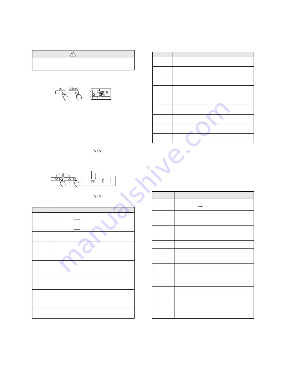
[SELF-DIAGNOSIS]
When the error indication "E:EE" is displayed, follow the following
items to perform the self-diagnosis. "E:EE" indicates an error has
occurred.
1. REMOTE CONTROLLER DISPLAY
(1) Stop the air conditioner operation.
(2) Press the set temperature buttons
simultaneously for 5
seconds or more to start the self-diagnosis.
Refer to the following tables for the description of each error
code.
SU MO TU WE TH FR SA
(3) Press the set temperature buttons
simultaneously for 5
seconds or more to stop the self-diagnosis.
Error code
Error contents
Communication error
(indoor unit
remote controller)
Communication error
(indoor unit
outdoor unit)
Room temperature sensor open
Room temperature sensor short-circuited
Indoor heat exchanger temperature sensor open
Indoor heat exchanger temperature sensor short-
circuited
Outdoor heat exchanger temperature sensor
Power source connection error
Float switch operated
Outdoor temperature sensor
Discharge pipe temperature sensor
00
01
02
03
04
05
06
08
09
0A
0c
Error code
Error contents
Model abnormal
Indoor fan abnormal
Outdoor signal abnormal
Outdoor EEPROM abnormal
Compressor temperature sensor
Pressure switch abnormal
IPM error
Compressor cannot operate
Outdoor fan abnormal
2. OUTDOOR UNIT LEDS
Heat & Cool model (reverse cycle) only
When a malfunction occurs in the outdoor unit, the LED on the circuit
board door unit, the LED on the circuit board light to indicate the error.
Refer to the following table for the description of each error accor-
ding to the LED.
LED1
Error contents
Unit number (usually 0)
Error code
Test run display
11
12
13
14
15
16
17
1b
1A
EX. Self-diagnosis
10
2005.04.15
Summary of Contents for RD-45LA
Page 14: ...37 455 553 846 236 237 823 824 3 815 2 824 5 815 1 38 Models RD 45LA RD 54LA 13 2005 05 31 ...
Page 15: ...1 6 7 5 2 3 4 3 Models RO 45LA RO 45LB RO 54LA 14 2005 05 31 ...
Page 16: ...16 13 12 11 10 9 15 8 14 15 2005 05 31 Models RO 45LA RO 45LB RO 54LA ...
Page 17: ...22 20 21 23 24 19 17 18 26 25 16 2005 05 31 Models RO 45LA RO 45LB RO 54LA ...
Page 18: ...31 38 27 34 35 36 28 39 40 41 30 32 29 33 37 17 2005 05 31 Models RO 45LA RO 45LB RO 54LA ...
Page 22: ...0502G2762 ...


