


12
ECNO: 622
6. OPERATION
6.2 Preparation Prior to Measurement (Zero Adjustment, etc.)
Detector selection standard
Power ON
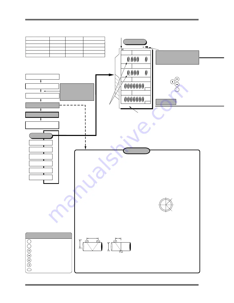
ENT
x10
x10
M3/h
m/s
ml
ml
99-05-11 11:49
×
1
×
2
×
4
×
8
Status display
x10
0
= 0
x10
1
=10
x10
2
=100
Example)
1.200
x10
2
corresponds to l.2 x 100 = 120m /h.
ENT
ESC
: ENTRY key (data registration)
: ESCAPE key (setting suspension)
: Cursor up-shift (set value feed)
: Cursor down-shift (set value return)
: Cursor left-shift (scale change)
: Cursor right-shift (scale change)
: Display screen printout (hard copy)
Description of key symbols
45
°
45
°
D
D
1) Straight piping greater than 10D must exist
on the upstream side and greater than 5D
on the downstream side.
2) Elements (pump, valve, etc) on the
upstream side must be greater than 30D
away to prevent disturbances
3) The piping must be filled with fluid free from
air bubbles and foreign objects.
Important!
Method of mounting for small sensor
(standard) and small diameter
sensors
(refer to Page 7 of this manual)
Selection of detector mounting
position
Selection of mounting method
r
o
t
c
e
t
e
D
e
p
y
T
)
m
m
(
r
e
t
e
m
a
i
d
e
d
i
s
n
I
(
°
C
e
g
n
a
r
e
r
u
t
a
r
e
p
m
e
T
)
r
o
s
n
e
s
r
e
t
e
m
a
i
d
ll
a
m
S
2
2
D
L
F
0
0
1
o
t
3
1
0
0
1
o
t
0
4
–
–
–
–
–
0
0
1
o
t
0
4
0
8
o
t
0
4
0
8
o
t
0
4
0
0
2
o
t
0
4
r
o
s
n
e
s
)
d
r
a
d
n
a
t
s
(
ll
a
m
S
2
1
D
L
F
0
0
4
o
t
0
5
r
o
s
n
e
s
e
g
r
a
L
1
5
D
L
F
0
0
0
6
o
t
0
0
2
0
0
2
1
o
t
0
0
2
r
o
s
n
e
s
e
r
u
t
a
r
e
p
m
e
t
-
h
g
i
H
2
3
D
L
F
0
0
4
o
t
0
5
FLD41
Middle sensor
* Straight piping greater than 10D must exist on the upstream side and greater than
5D on the downstream side.
* Elements (pump, valve, etc) on the upstream side must be greater than 30D away
to prevent disturbances.
When the power is ON, the
language select screen is
displayed. Select the
language to be used and
then press the ENT key.
Piping specification input
Sensor mounting
Measurement start
Measurement end
/Power OFF
Measurement
Site setup
Data logger
System setup
Printer
Analog
System check
Measurement
(Measurement cycle: Once/sec)
Indicator (receiving wave strength)
More than 2 indicators for standard
measurement. When one or no indicator
is working, the transmission voltage
should be raised.
Zero Adjustment
L = About D
L = About D/2
V method
Z method
L: Mounting size
Treatment of detector mounting side
•
Using thinner and sand-paper, remove the
pitches, rust and uneven surface of the detector
mounting piping over the entire mounting area
of (L) + 200mm wide.
•
When the piping exterior is wrapped with jute,
remove the jute and then perform the above
treatment.
•
Horizontal piping should be mounted within
±
45
°
from the horizon.
•
Vertical piping can be mounted at any external
position.
• Insufficient mounting space (about 1/2 of the size of
the V method)
Small diameter sensor and small type (standard)
sensor should be mounted by the V method.
In the following cases, the Z method should be
used for mounting.
• Piping with mortar lining
• Piping is old and presumed to have a deposit of a thick
layer of scales inside the piping.
1) Loosen the lock nut. After setting to the
mounting position, tighten the lock nut.
2) Coat the sensor transmission side with a
sufficient amount of silicone grease.
3) Attach both ends (saddle) to the piping
using a cloth belt.
4) Make sure that the sensor is mounted in
parallel with the piping and that the
mounting position is correct. Then, turn the
element holder clockwise until the sensor is
firmly fitted to the piping (clockwise;
element moves down, anti-clockwise;
element moves up).
3
RESET
STOP
RESET
STOP
FLOW RATE
UNIT:
VELOCITY
UNIT:
+TOTAL
UNIT:
–TOTAL
UNIT:
MEASURE
NORMAL
Battery alarm
(1)
(3)
(4)
(2)


