


58
The AC/DC drive profile implementation provides support for several required CIP objects, which are
specified in Table 22. While the various supported attributes of all of these objects are accessible via
explicit messaging, the main intent of using the AC/DC drive profile is to interact with the predefined
input and output assembly instances via an I/O connection. The structure of these assembly instances is
defined by the EtherNet/IP specification in order to engender interoperability among different vendor’s
products. This section will focus primarily on the format of the AC/DC drive profile I/O assemblies
supported by the interface card, and the inverter data which their various constituent elements map to.
Table 22: AC/DC Drive Profile-Related Objects
Class Code
Object Name
0x04
Assembly Object
0x28
Motor Data Object
0x29
Control Supervisor Object
0x2A
AC Drive Object
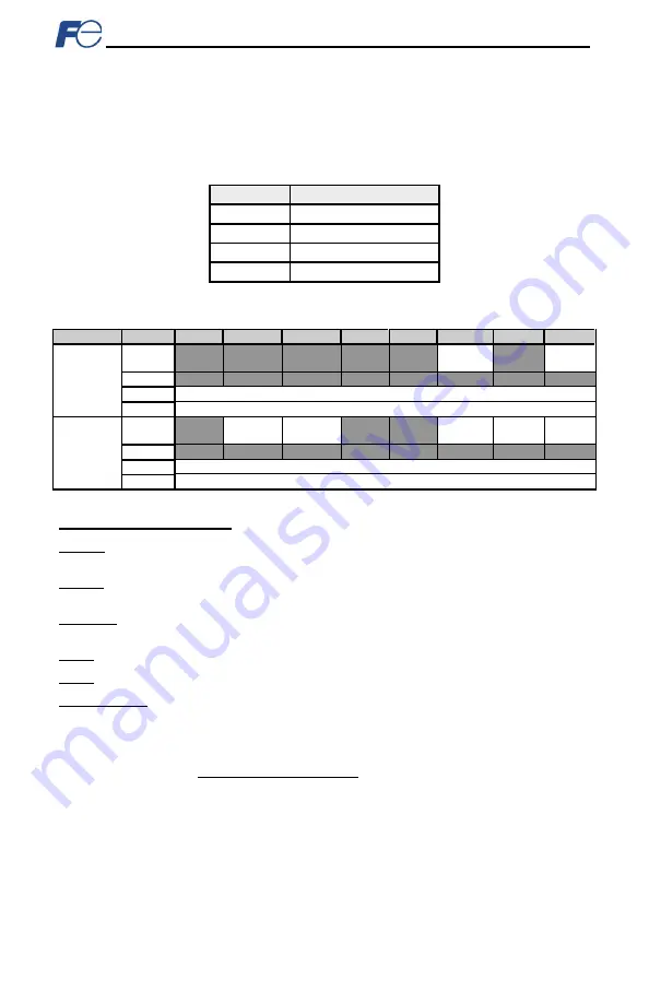
Table 23: Output Instances 20 and 21 Detail
Instance
Byte
Bit 7
Bit 6
Bit 5
Bit 4
Bit 3
Bit 2
Bit 1
Bit 0
20
0
Fault
Reset
Run
Fwd
1
2
Speed Reference (Low Byte)
3
Speed Reference (High Byte)
21
0
NetRef
NetCtrl
Fault
Reset
Run
Rev
Run
Fwd
1
2
Speed Reference (Low Byte)
3
Speed Reference (High Byte)
Output Instance Mapping Detail
Run Fwd: forward rotation command (0=forward rotation off, 1=forward rotation on). Maps to inverter
function code S06, bit 0 (function code S06 / operation command word, FWD bit).
Run Rev: reverse rotation command (0=reverse rotation off, 1=reverse rotation on). Maps to inverter
function code S06, bit 1 (function code S06 / operation command word, REV bit).
Fault Reset: Inverter reset command (0=n
o action, 0→1 rising edge=reset). Maps to inverter function
code S06, bit 15 (function code S06 / operation command word, RST bit).
NetCtrl: Not used (value is ignored).
NetRef: Not used (value is ignored).
Speed Reference: Inverter speed reference in RPM. Maps to function code S05 (frequency command).
The speed reference component of the AC/DC drive profile output instances is always in units of RPM.
Therefore, the interface card applies the RPM-to-Hz conversion indicated in Equation 5 in order to
determine the appropriate frequency command value (in units of Hz) to be written to function code S05.
120
poles
motor
of
number
x
RPM
Hz
=
Equation 5
The “number of motor poles” term which appears in the numerator of Equation 5 is obtained from the
setting of inverter function code P01 (Motor number of poles). Note that the value of P01 is read by the
interface card only at boot-up, so if the value of this function code is changed, then the interface card
must be rebooted in order for it to read the new value from the inverter.


