PID SET UP WITH FRENIC Eco series inverter.
1
PID SET UP WITH FRENIC Eco series inverter.
1. Introduction.
This document describes briefly how to set up the FRENIC Eco series inverter to
implement a PID control, for example, a pressure control with a pump, where the
pump is moved by a motor controlled by a FRENIC Eco inverter.
2. Preparation.
Before setting up a PID controller few items have to be checked. As an example we
will describe a set up for controlling pressure.
•
Is the sensor capable of sensing the expected range?
When we want to control the pressure in a system to 2 Bar, the sensor must
be capable of measuring more. Preferably 1.5 times more, i.e. 3 Bar.
•
Does it have an output signal that can be connected directly to the FRENIC
Eco input?
FRENIC Eco has inputs for 0-10 V and 4-20 mA signals.
3. PID Basics.
3.1 PID Basic Concept.
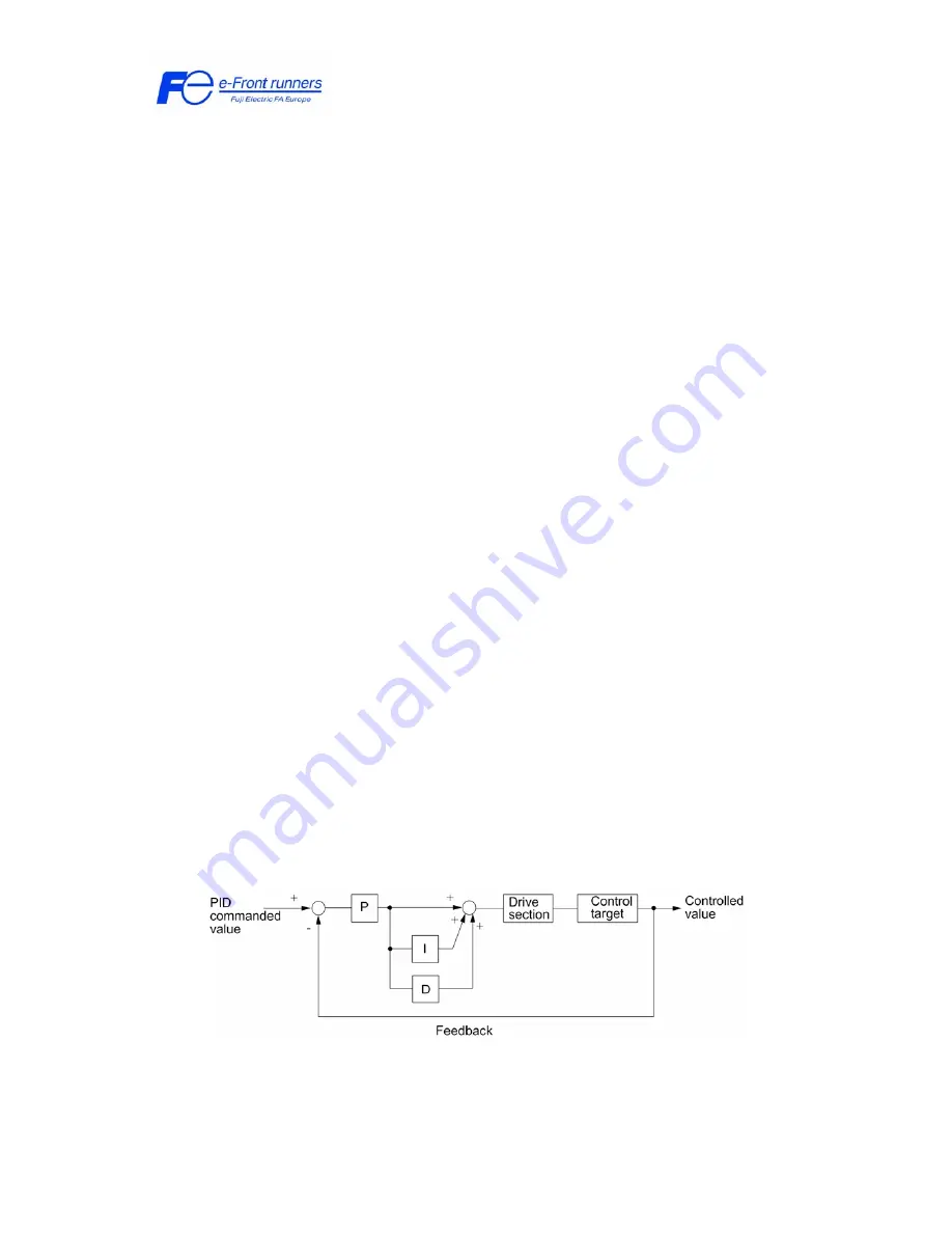
A PID regulator is a control structure that will try to control a certain magnitude
(pressure, flow rate, temperature, ...) to a desired value, which is called
PID
command
(or set-point) value. To do so this structure needs information of the actual
status of the system by means of the proper measurement device (pressure, flow or
temperature sensor). This signal is called the
PID Feedback
. This control structure
normally has three control actions: Proportional (P), Integral (I) and Derivative (D)
that have to be tuned according to the real system.
Figure 1. PID control structure diagram.
What happens in this picture?


