Chapter 3 TEST RUN PROCEDURE
3.1 Checking Prior to Powering On
Check the following before powering on the dynamic breaking unit.
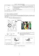
(1) Check the wiring to the inverter P(+)-N(-) line connecting terminals and external braking resistor connecting terminals
DB1, DB2, and DB3. Also check that the grounding wires are connected to the grounding terminals ( G) correctly.
• Never connect power supply wires to the external braking resistor connecting terminals DB1, DB2, and DB3. Doing so
and turning the power ON breaks the dynamic breaking unit.
• Be sure to connect the grounding wires of the dynamic breaking unit to the ground electrodes.
Otherwise, an electric shock could occur.
(2) Check the control circuit terminals and main circuit terminals for short circuits or ground faults.
(3) Check for loose terminals, connectors and screws.
3.2 Powering ON and Checking
• Be sure to mount the front cover before turning the power ON. Do not remove the cover when the dynamic breaking unit
power is ON.
• Do not operate switches with wet hands.
Otherwise, an electric shock could occur.
Check the followings before power-on.
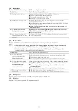
(1) Check that the charging lamp is turned ON.
(2) Check that the Relay output [Y5A/C] is turned ON (
Ready to run)
.
(3) Check that the Alarm relay output [30A/B/C] is turned OFF.
Chapter 4 TROUBLESHOOTING
4.1 Protective Functions
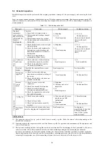
The dynamic breaking unit has various protective functions to prevent the system from going down and reduce system
downtime.
If any problem arises, follow the procedures given in Section 4.2 and onwards for troubleshooting.
4.2 Before Proceeding with Troubleshooting
• If any of the protective functions has been activated, first remove the cause. Then, after checking that the all run
commands are set to OFF, release the alarm. If the alarm is released while any run commands are set to ON, the
inverter may supply the power to the motor, running the motor.
Injury may occur.
• Even if the inverter has interrupted power to the motor, if the voltage is applied to the main DC input terminals P(+)
and N(-), voltage may be output to inverter output terminals U, V, and W.
•
Turn the power OFF, wait at least ten minutes,
and make sure that the charging lamp are turned OFF. Further,
make sure, using a multimeter or a similar instrument, that the DC link bus voltage between the terminals P(+) and
N(-) has dropped to the safe level (+25 VDC or below).
Electric shock may occur.
Follow the procedure below to solve problems.
(1) First, check that the dynamic breaking unit is correctly wired, referring to Chapter 2, Section 2.3.5 "Wiring of main
circuit terminals and grounding terminals."
(2) If the Alarm relay output [30A/B/C] is turned ON, Go to Section 4.3. The protective functions has been activated.
If any problems persist after the above recovery procedure, contact your Fuji Electric representative.
21
Summary of Contents for BUC S-69D
Page 8: ......


