10
Air Circuit Breakers
BT2 series
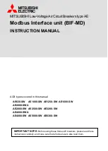
Ground-fault protection
• Definite ground-fault protection, and its setting current Ir4 can be adjusted
• Delay time t4 can be adjusted
• Alarm but not break after being off
I
t
Setting current Ir
4
of ground-fault
Setting current t
4
of ground-fault
• TN-C, TN-C-S, or TN-S, power distribution system
without additional current transformer of neutral
• TN-S, power distribution system, 4 poles
• TN-S, power distribution system, 3 poles
L
1
PEN
L
2
L
3
Intelligent
controller
BT2 circuit breaker with three poles
Transformer
Current transformer
For exmple : TN-C system
N
PE
L
1
L
2
L
3
Intelligent
controller
Transformer
Current transformer
For example: TN-S system
BT2 circut breaking with four poles
N
PE
L
1
L
2
L
3
N line current transformer
connected externally
Transformer
Current transformer
Intelligent
controller
For example: TN-S system
BT2 circut breaking with three poles
t
I
t
I
Setting current I
LC2
of load monitoring (Limiting load)
Setting current I
LC1
of load monitoring (Limitiong load)
Setting delay time t
c1
of load monitoring
Setting delay time t
c2
of load monitoring
Acting characteristic of two kinds of ultimate setting load
t
I
t
I
Setting current I
LC2
of load monitoring (reload)
Setting current I
LC1
of load monitoring (Limiting load)
Setting delay time t
c2
of load monitoring
Setting delay time t
c2
of load monitoring (definite)
Acting characteristic of ultimate setting value of load and reload
• Pattern 1: Two circuits of down stream load can be controlled.
When the operating current of the main circuit rises over the
setting value of I
LC1
and I
LC2
, contact signal will be sent out
after time durations of t
C1
and t
C2
repectively. Then this two
circuits with monitored load are broken off by receiving the
instructions from the intelligent controller.
• Pattern 2: Only one circuit with down stream load can be
controlled. When the operating current of the main circuit
rises over the setting value of I
LC1
, contact signal will be sent
out after time duration of t
C1
, and this circuit is broken off by
receiving the instructions from the intelligent controller. If the
operating current of the main circuit decreases lower than
the setting value of I
LC2
after this circuit is broken off, the
signal will be sent out again after time duration of t
C2
for the
open loading circuit to be closed (reloaded) and so the power
supply of this circuit is restored.
• Load monitoring signals"(1)" and "(2)" corresponding to I
LC1
and I
LC2
respectively are transmitted into contact signals
via the wiring terminals 13, 14 and 15, 16 of the secondary
circuit. There will be LED indication at the time when signals
are transmitted. (The load monitoring signals from the
intelligent controller will be cut off in half second after the
signal of contact closing is transmitted, and the capacity of
contact is AC230V 5A)
Load monitoring function
• To monitor the down stream load so as to ensure power
supply of main system
• There are two patterns of load monitoring from which users
can choose one. The setting value of load-monitoring current
are I
LC1
and I
LC2
, normally I
LC1
is larger than or equal to I
LC2
• Inverse characteristic of load-monitoring is the same of
inverse long-time delay overload characteristic.
Intelligent controller