background image

C1 x 6

C2 x 6

A x 2 

B x 8 

J1 x 1 

J2 x 1 

6 x 30 mm

4 x 40 mm

4 x 12 mm

C1

C1

C1

C1

C1

C1

C2

C2

C2

C2

C2

C2

2

3

A

A

B

B

B

B

B

B

B

B

B

1

3

5

9

5

J1

J2

J2

C2

C1

6/11

3

4

Knock part(

C1

,

C2

)

 slightly 

into the holes 

i

n panel 2&3


as shown.


Fix part

(

J1

)

 to panel 1 using screw

(

J2

)

. Connect panel 

1 with panel 3 using wooden dowel

(

A

)

 at first. Then 

use screw

(

B

)

 to tighten, as shown.

Attach panel 5 and 9 to panel 3 using screw

(

B

)


as 

shown

.

3

Summary of Contents for KF200198-01

Page 1: ...ersion 05 27 2022 Shoe Cabinet V 1 11...

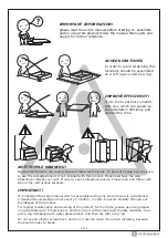
Page 2: ...a rag dampened with water glass cleaner and then dry with a dry rag Do not use an electric screwdriver and do not use too much force when installing because the board is easy to break IMPORTANT Overtu...

Page 3: ...nual accessories with similar shapes can be distinguished by size Please prepare the following tools 3 11 A x 4 4 x 40 mm B x 17 C1 x 6 C2 x 6 C3 x 6 3 5 x 14 mm D x 36 4 x 10 mm E x 6 4 x 20 mm F x 6...

Page 4: ...4 11 x3 5 2 9 7 7 8 5 1 3 4 6...

Page 5: ...L D R 8 D D L Fix plastic part L R to panel 8 using screw D as shown Attach panel 7 to the assembled part using screw D slightly to tighten as shown D Attach this part to panel 6 using screw D to cor...

Page 6: ...A A B B B B B B B B B 1 3 5 9 5 J1 J2 J2 C2 C1 6 11 3 4 Knock part C1 C2 slightly into the holes in panel 2 3 as shown Fix part J1 to panel 1 using screw J2 Connect panel 1 with panel 3 using wooden d...

Page 7: ...5 x 14 mm A A B B B B B B B B 1 2 3 5 9 5 B H H H H I I I I I I I I I 3 2 4 I I 1 Attach panel 2 to assembled part in step 4 using screw B and wooden dowel A Fix panel 4 to the back of assembled unit...

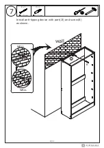
Page 8: ...B x 1 J3 x 1 4 x 40 mm 6 x 30 mm wall 1 B 7 8 11 WALL WALL J3 Install anti tipping device with part J3 and screw B as shown...

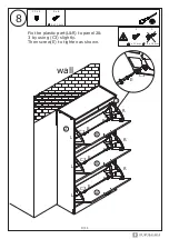
Page 9: ...6 4 x 10 mm E D 3 5 x 14 mm 4 x 10 mm 8 9 11 E x 6 Fix the plastic part L R to panel 2 3 by using C3 slightly Then screw E to tighten as shown wall 2 L 3 C3 E R C3 E L C3 E R C3 E L C3 E R C3 E 6 C3 E...

Page 10: ...9 10 11 Insert panel 7 to the middle of drawers wall 7 7 7...

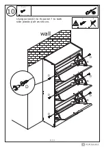
Page 11: ...D x 6 3 5 x 14 mm 10 11 11 Using screw D to fix panel 7 to both side plastic part as shown wall 7 7 7 D D L R D D L R D D L R D E D 3 5 x 14 mm 4 x 10 mm...

Page 12: ......

Page 13: ......

Reviews: