background image

8

10/13

III

II

I

4

3

2

2

6 x 30 mm

F x 6

E x 6

15 x 9 mm

E

E

E

E

E

E

E

F

F

F

F

F

F

F

F

Attach No.2 plate to the top of the 

component using wooden dowel(F),

then turn cam lock(E) in No.3,4,5 

plates clockwise to tighten as shown.

180°

Summary of Contents for KF200165

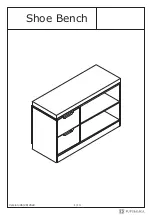
Page 1: ...Shoe Bench Version 06 28 2022 1 13...

Page 2: ...a rag dampened with water glass cleaner and then dry with a dry rag Do not use an electric screwdriver and do not use too much force when installing because the board is easy to break IMPORTANT Overtu...

Page 3: ...w corresponds to the manual accessories with similar shapes can be distinguished by size Please prepare the following tools 3 13 CL x 2 CR x 2 C x 16 D x 22 3 x 12 mm 6 x 35 mm 6 x 30 mm 4 x 35 mm 3 x...

Page 4: ...4 13 1 2 9 4 6 5 7 3 8 8 12 13 11 14 10 X2...

Page 5: ...D D D D D D D D D D D D D C C C C C C C CR CL C Fix slide rail CL and CR to No 3 and No 4 plate with screw C as shown Insert quickfit screw D into corresponding holes in No 3 and No 4 plate with a sc...

Page 6: ...3 6 13 15 x 9 mm E x 4 6 x 30 mm F x 4 III II I 7 7 E E E E E F F F F F 8 8 8 8 Attach No 8 plate to No 7 with wooden dowel F then turn cam lock E in No 8 plate clockwise to tighten as shown 180...

Page 7: ...30 mm F x 2 4 x 35 mm G x 2 6 x 30 mm F x 2 4 7 F F G G G F F F 4 4 7 6 6 Connect No 4 plate with No 7 using wooden dowel F then fix with screw G as shown Connect No 6 plate with No 4 using wooden dow...

Page 8: ...8 13 III II I 6 x 30 mm F x 4 4 5 5 7 7 6 E x 2 15 x 9 mm E E E F F F F Connect No 5 plate with No 6 and No 7 using wooden dowel F then turn cam lock E in No 7 plate clockwise to tighten as shown 180...

Page 9: ...7 9 13 III II I 4 3 3 7 7 6 x 30 mm F x 2 E x 2 15 x 9 mm E E E F F F F Connect No 3 plate with No 7 using wooden dowel F then turn cam lock E in No 7 plate clockwise to tighten as shown 180...

Page 10: ...I 4 3 2 2 6 x 30 mm F x 6 E x 6 15 x 9 mm E E E E E E E F F F F F F F F Attach No 2 plate to the top of the component using wooden dowel F then turn cam lock E in No 3 4 5 plates clockwise to tighten...

Page 11: ...m G x 8 3 9 2 H H H H H H H H H H H H H H H H H H H G G G G G G D D DD D D X2 12 13 11 10 Fix No 9 back plate using screw H as shown Attach No 11 and No 12 plate to No 13 with screw G as shown Insert...

Page 12: ...12 12 13 11 11 14 14 14 10 10 180 E E E E E E DR DR C C DR C C C C DL Slide No 14 plate into available slots as shown Attach No 10 plate to the component and turn cam lock E clockwise to tighten as s...

Page 13: ...13 13 13 2 2 3 1 3 10 10 Align rails slide drawers Put pad at the top...

Page 14: ......

Page 15: ......

Reviews: