background image

15 x 10 mm

6 x 40 mm

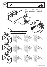
B x 6

H x 2

B

B

B

B

B

B

B

H

H

H

11

11

180°

10

10

12

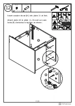
Insert wooden dowel(H) into plate 11 at first.

Attach plate 10 to plate 11,12 and turn cam 

locks(B) clockwise to tighten as shown.

12

12

15/26

Summary of Contents for KF200147

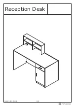
Page 1: ...Reception Desk Version 08 12 2022 1 26...

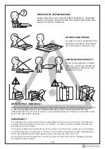
Page 2: ...a rag dampened with water glass cleaner and then dry with a dry rag Do not use an electric screwdriver and do not use too much force when installing because the board is easy to break IMPORTANT Overtu...

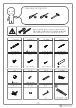
Page 3: ...x 18 mm 6 x 40 mm M5 x 40 mm M6 x 30 mm M6 x 12 mm K x 2 L x 1 SET N x 8 1 J x 4 M x 1 60 mm M4 x 18 mm 4 14 3508W 1SET When installing please carefully confirm whether each screw corresponds to the...

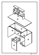
Page 4: ...1 2 3 4 5 6 6 7 8 9 10 11 12 12 14 13 15 17 16 18 19 21 20 4 26...

Page 5: ...5 26...

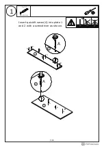
Page 6: ...1 A x 12 M5 x 42 mm Insert quickfit screw A into plate 1 and 2 with a screwdriver as shown A A A A A A A A A A A A A A 1 1 2 2 6 26...

Page 7: ...2 A A A A A A A A A A A A Insert quickfit screw A into plate 3 4 5 with a screwdriver as shown Please note both sides of plate 4 need to be inserted A x 8 M5 x 42 mm 3 3 4 4 4 5 5 7 26...

Page 8: ...B x 4 Connect plate 3 and 4 with plate 6 and turn cam locks B clockwise to tighten as shown B B B B B 180 4 6 6 3 Connect plate 4 and 5 with plate 6 and turn cam locks B clockwise to tighten as shown...

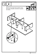
Page 9: ...5 15 x 10 mm B x 4 Attach the component to plate 2 and turn cam locks B clockwise to tighten as shown 4 5 6 6 3 2 6 2 B B B B B 9 26 180...

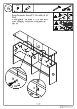
Page 10: ...10 mm B x 8 H x 2 2 2 1 2 3 4 1 5 B B B B B B B B B H H H 6 x 40 mm Insert wooden dowel H into plate 2 at first Cover plate 1 to plate 2 3 4 5 and turn cam locks B clockwise to tighten as shown 1 10...

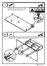
Page 11: ...5 x 40mm 8 D x 6 7 7 7 3 5 4 4 7 A A A A A D D D D D D D D A A Insert quickfit screw A into plate 7 with a screwdriver as shown A x 6 M5 x 42 mm Attach plate 7 to plate 3 4 5 with screw D as shown 11...

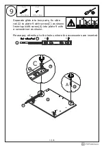
Page 12: ...C C A A A A A A Separate glide into two parts fix slide rail 22 to plate 9 with screw C as shown Insert quickfit screw A into plate 9 with a screwdriver as shown Please pay attention to the holes whe...

Page 13: ...C C C C A A A A A A A C 22 22 22 10 10 10 22 Fix slide rail 22 to plate 10 with screw C as shown Insert quickfit screw A into plate 10 with a screwdriver as shown Please pay attention to the holes whe...

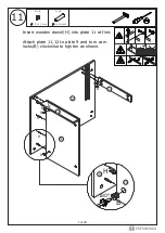
Page 14: ...5 x 10 mm 6 x 40 mm B x 6 H x 2 B B B B B B B H H H 11 11 9 9 Insert wooden dowel H into plate 11 at first Attach plate 11 12 to plate 9 and turn cam locks B clockwise to tighten as shown 180 12 12 14...

Page 15: ...10 mm 6 x 40 mm B x 6 H x 2 B B B B B B B H H H 11 11 180 10 10 12 Insert wooden dowel H into plate 11 at first Attach plate 10 to plate 11 12 and turn cam locks B clockwise to tighten as shown 12 12...

Page 16: ...m A x 6 A A A A A A A 13 14 13 13 M5 x 42 mm A x 6 Insert quickfit screw A into plate 13 with a screwdriver as shown Insert quickfit screw A into plate 14 with a screwdriver as shown A A A A A A A 14...

Page 17: ...B B B B H 9 9 14 14 14 10 14 13 13 13 B x 8 15 x 10 mm H x 8 6 x 40 mm 6 x 40 mm Connect plate 13 and 14 with wooden dowel H as shown Attach plate 13 14 to plate 9 10 with wooden dowel H and turn cam...

Page 18: ...17 H H H H B B B B 8 14 13 B x 4 15 x 10 mm H x 4 6 x 40 mm Attach plate 8 to plate 13 14 with wooden dowel H and turn cam locks B clockwise to tighten as shown H B 180 18 26...

Page 19: ...18 M6 x 12 mm E x 4 E E E E E E 8 8 9 10 Connect plate 8 and 9 with iron tube 21 using screw E as shown 21 21 19 26...

Page 20: ...7 9 10 B x 6 15 x 10 mm H x 6 6 x 40 mm F x 2 M6 x 30 mm Attach plate 7 to plate 8 9 10 with wooden dowel H and turn cam locks B clockwise to tighten as shown Fix iron tube 21 to plate 7 with screw F...

Page 21: ...20 C C C C K J J K J J L C C L L 20 20 20 C x 4 M3 5 x 12 mm K x 1 L x 1 SET J x 2 M4 x 18 mm Fix hinge L to plate 20 with screw C fix handle K to plate 20 with screw J as shown 21 26...

Page 22: ...21 C C C 20 20 10 10 C x 8 M3 5 x 12 mm Attach plate 20 to 10 by fixing hinge with screw C as shown 22 26...

Page 23: ...K G G M G x 4 M3 x 18 mm M x 1 Fix part M to plate 15 with screw G as shown A x 4 M5 x 42 mm K x 1 J x 2 M4 x 18 mm Insert quickfit screw A into plate 15 with a screwdriver as shown Fix handle K to p...

Page 24: ...19 24 25 B x 4 Slide plate 19 into available slots as shown 15 x 10 mm Attach plate 16 17 to plate 15 and turn cam locks B clockwise to tighten as shown 17 15 16 B B B 180 B B B 24 26...

Page 25: ...26 27 17 17 17 18 16 16 22 22 C D D D D D D C C C C C x 4 D x 4 M3 5 x 12 mm M5 x 40 mm Fix runner 22 to plate 16 17 with screw C as shown Attach plate 18 to plate 16 17 with screw D as shown 25 26...

Page 26: ...28 29 60 I x 1 N x 8 Align rails slide the drawer Align the wire box I into the hole position I I 15 Cover cam locks B using sticker N as shown N N 26 26...

Page 27: ...or health reasons For other reasons if the furniture needs to be returned it must be cleaned and dried and operated within 30 days of receipt Type of Warranty Claim Failure to follow the furniture ins...

Page 28: ...eive an order with obvious shipping damage from the retailer then we suggest the delivery is refused If the delivery has been accepted and then shipping damage is found please follow the specific inst...

Reviews: