background image

Dx8


Ø4x35mm

Cx8


Ø6x30mm

C

C

D

D

C

C

D

D

C

C

D

D

C

C

D

D

D

13

12

11

11

9

9

8

1

5

6

4

3

6

2

8

13/28

Cover No.8 plate to the component using 

wooden dowel(C) and fix with screw(D) as 

shown.

Summary of Contents for KF020309-01

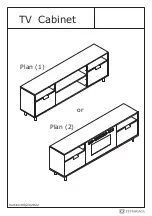
Page 1: ...TV Cabinet or Plan 1 Plan 2 Version 09 23 2022 ...

Page 2: ... with a rag dampened with water glass cleaner and then dry with a dry rag Do not use an electric screwdriver and do not use too much force when installing because the board is easy to break IMPORTANT Overturned furniture can cause serious or fatal crush injuries To prevent tipping over be sure to use the wall attachment if not included with this product Please purchase the wall attachment that fit...

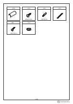
Page 3: ...x16mm Ø3x12mm Hx20 1 Ø3 5x10mm Jx4 Kx24 1 Lx4 Mx2 Nx8 Px12 3 28 Ø3x16mm Qx12 Rx4 Ø4x35mm Ø3 5x10mm Please prepare the following tools When installing please carefully confirm whether each screw corresponds to the manual accessories with similar shapes can be distinguished by size ...

Page 4: ...Sx4 Wx2 Tx6 Ux2 Vx2 Yx4 4 28 Ø3x12mm Ø4x14mm Ø6x30mm ...

Page 5: ...1 2 3 4 5 6 7 6 11 11 12 15 15 8 14 14 13 13 14 14 16 17 9 9 10 9 9 10 5 28 ...

Page 6: ...Fx2 1 F F F3 F1 F2 F2 F3 F1 Ex3 F1 2 Ex6 Ø3 5x10mm F1x2 F1 E E E x2 2 5 5 6 28 Separat part F into 3 parts as shown Fix part F1 to No 2 and No 5 with screw E as shown ...

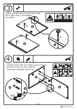
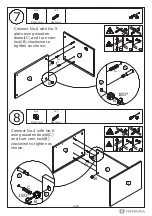
Page 7: ...Ø6x30mm I II III 3 4 B B A A A A C C 2 6 2 B C 180 6 2 7 28 Insert quickfit screw A into No 2 and No 3 plate with a screwdriver as shown Connect No 6 with No 2 plate using wooden dowel C and turn cam lock B clockwise to tighten as shown ...

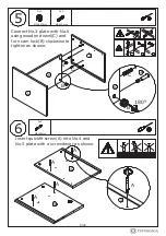
Page 8: ...mm 5 I II III C B C B 6 2 3 6 Ax4 Ø6x35mm 6 5 4 4 3 8 28 180 Connect No 3 plate with No 6 using wooden dowel C and turn cam lock B clockwise to tighten as shown Insert quickfit screw A into No 4 and No 5 plate with a screwdriver as shown ...

Page 9: ...10mm Ø6x30mm C C B B B C C C B B C B 6 5 6 5 4 6 5 6 4 9 28 180 180 Connect No 6 with No 5 plate using wooden dowel C and turn cam lock B clockwise to tighten as shown Connect No 4 with No 6 using wooden dowel C and turn cam lock B clockwise to tighten as shown ...

Page 10: ...C C C C C Ax8 Ø6x35mm A A A A A A A A A 10 2 6 3 4 4 6 5 1 1 10 28 Insert wooden tenon C into No 2 No 3 No 4 and No 5 plate as shown Insert quickfit screw A into corresponding holes in No 1 plate with a screwdriver as shown ...

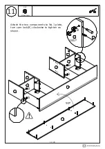
Page 11: ...Bx8 Ø15x10mm B B B B B B B B 5 6 4 3 2 6 90 11 5 B 1 1 1 11 28 180 Attach the two components to No 1 plate turn cam lock B clockwise to tighten as shown ...

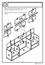
Page 12: ...12 9 9 9 9 9 9 9 9 10 10 10 10 12 12 11 11 11 11 5 6 4 1 3 6 2 12 28 Please combine two No 9 plate with No 10 two No 11 plate with No 12 at first Slide the back plate into available slots as shown ...

Page 13: ...Dx8 Ø4x35mm Cx8 Ø6x30mm C C D D C C D D C C D D C C D D D 13 12 11 11 9 9 8 1 5 6 4 3 6 2 8 13 28 Cover No 8 plate to the component using wooden dowel C and fix with screw D as shown ...

Page 14: ...Hx20 Gx4 G G G G Hx5 Hx5 Hx5 Hx5 G H H H H H 14 8 8 5 6 4 3 6 2 1 14 28 Fix iron sheet G to No 8 plate with screw H as shown Ø3x16mm ...

Page 15: ...G G G G G 15 8 5 6 4 3 6 2 1 8 14 14 14 13 13 14 14 13 15 28 Rotate No 14 legs into the iron sheet part Rotate No 13 leg support into No 8 plate as shown ...

Page 16: ...Mx2 M M M 16 8 5 6 4 3 6 2 1 14 14 13 13 14 14 Y Y Y Y Y Yx4 14 Y 8 13 16 28 Rotate part M into No 13 leg support as shown Cover foot peg Y to No 14 leg ...

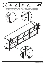
Page 17: ...Q P Q P Q P P Q 17 P Q P Q P Q P Q P Q P Q P Q P Q 5 1 9 9 9 9 11 11 9 9 Vx2 Wx2 W V W V 2 1 5 9 V W 17 28 Reinforce back plates using part P and screw Q as shown Fix part V to No 2 and No 5 plate with screw W as shown Ø4x14mm ...

Page 18: ...18 M 2 3 1 8 4 5 14 13 13 14 6 6 1 2 3 4 5 11 11 9 13 8 18 28 If the item is unstable or the bottom plate sinks Please adjust part M at the bottom of No 13 leg support ...

Page 19: ... Kx2 F2x2 Jx4 Kx8 Rx4 Ø3 5x10mm Sx4 17 17 17 16 16 16 19 28 Fix hinge J to No 16 and No 17 plate respectively with screw K as shown Fix part F2 to No 16 and No 17 plate respectively with screw E as shown Fix handle S to No 16 and No 17 plate respectively with screw R as shown Ø3x12mm ...

Page 20: ...J Kx4 J Kx4 J Kx4 J J K Kx16 F2 F1 F2 F1 F3 K K K 17 17 16 2 3 1 8 4 5 8 20 28 Attach No 16 door plate to left No 17 to right by fixing hinge with screw K as shown Combine all parts of accessory F as shown Ø3x12mm ...

Page 21: ...21 F3 F3 F3 14 13 13 14 1 2 3 4 5 11 11 8 16 6 1 8 16 17 17 2 4 5 21 28 If the TV table door panel tilts or sinks please adjust part F3 ...

Page 22: ...his TV cabinet can be used in two ways Plan 1 is to add a removable plate that would be used only as a TV cabinet steps are in step 23 Plan 2 is to install a matching fireplace which can be used as a mantelpiece steps 24 to 27 ...

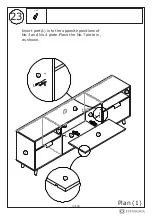
Page 23: ...23 Lx4 L L L L L Plan 1 4 4 2 3 1 8 7 7 5 23 28 Insert part L into the opposite positions of No 3 and No 4 plate Place the No 7 plate in as shown ...

Page 24: ...T T T fireplace shell T Step 2 24 Step 1 15 15 15 Plan 2 24 28 Please make sure you have bought a matching fireplace Remove the shell of the fireplace Connect No 15 plate with the fireplace using screw R Ø3x12mm ...

Page 25: ...the glass panel by aligning the 4 hooks until it snaps into position sinks down 1 2 cm Thread the matching screw into the threaded holes on the glass panel Check the alignment of the glass paneland securely tighten the screws Connect the datacable connector Plan 2 25 28 matching screw matching screw ...

Page 26: ...hind 26 Plan 2 1 2 3 8 4 5 16 17 fireplace 5 1 11 11 9 9 9 9 26 28 Push the fireplace vertically into the TV cabinet as shown Be careful to insert the fireplace plug through the round hole in No 11 plate ...

Page 27: ...N N N N N N N N N Nx8 Ø4x35mm Please use screw N to secure the fireplace to panels 3 and 4 as shown 27 Plan 2 1 2 3 4 16 17 8 8 8 3 5 27 28 ...

Page 28: ... it is recommended that you attach the TV cabinet to the wall Additional hardware D U V as shown Should you choose not to affix the product to the wall serious injury may be caused if the product tips over Ux2 Ø6x30mm WALL D D V V 1 2 5 8 D V 1 16 17 Take plan 1 as an example 28 28 ...

Page 29: ......

Page 30: ......

Reviews: