FTI SP22 Series Assembly, Installation And Operation Manual Download Page 9

9

Maintenance

Recommended maintenance schedule

The recommended maintenance schedule depends upon the 
nature of the fluid being pumped and the specific application  
If the pump is used on a clean fluid, it is recommended that the 
pump be removed from service and examined after six months 
of operation or after 2,000 hours of operation  If the pump is 
used on fluids with solids, high temperatures or other items that 
could cause accelerated wear this initial examination should be 
sooner 

After the initial examination of the internal components and wear 
items are measured, a specific maintenance schedule can be 
determined  For best results, it is recommended that the pump 
be removed from service annually for examination 

Section V - Disassembly

Tools Required:

3/8” Allen wrench or ballpoint hex socket, 3/16” Allen wrench,  
(2) flat head screw drivers, 10 mm hex socket, metric socket set 
(for pumps with IEC outer drives)  


WARNING:

  Rotating Parts  This pump has components that  

 rotate while in operation   Follow local safety standards for  


locking out the motor from the power supply during mainte- 


nance or service 

WARNING:

  Chemical Hazard  This pump is used for trans- 

 ferring many types of potentially dangerous chemicals   


Always wear protective clothing, eye protection and follow  


standard safety procedures when handling corrosive or per- 


sonally harmful materials  Proper procedures should be  


followed for draining and decontaminating the pump before  


disassembly and inspection of the pump  There may be  


small quantities of chemicals present during inspection 


WARNING

:  Magnetic force hazard  This pump should only  

 be disassembled and assembled using the recommended  


procedures   The magnetic attraction is powerful enough to  


rapidly pull the motor end and the wet end together   Do not  


place fingers between the mating surfaces of the motor and  


wet ends to avoid injuries   Keep the drive magnet and  


impeller assembly away from metal chips or particles 

1   Stop the pump, lock out the motor starter, close all the  
 

valves that are connected to the pump, and drain/decon- 


taminate the pump   


WARNING:

  The pump must be thoroughly flushed of any  

 hazardous materials and all internal pressure relieved prior  


to opening the pump  Allow the pump to reach ambient  


temperatures prior to performing maintenance 

2   Place the pump/motor on the floor with the pump facing  
 

up  Remove (4) 1/2” socket head cap screws, lock washers  


and flat washers (items 18, 19,  


20) securing the pump to the motor  Use 3/8” Allen wrench  


or 3/8” hex socket on universal joint  

3   Firmly grab the motor adapter and pull straight up to disen- 
 

gage the motor and pump  See figure 10  


For 182, 184, 213, and 215TC motor frame pumps, 

make  


sure the o-ring (item 12B) does not fall out of the motor  


adapter (motor end) 

4   Place pump on bench with housing (item 1) facing up  Using  
 

a 10 mm hex (Allen) wrench, remove (10) M12 socket head  


cap screws, lock washers and flat washers (items 15, 16,  


17)  See figure 11 

Figure 10

Figure 11


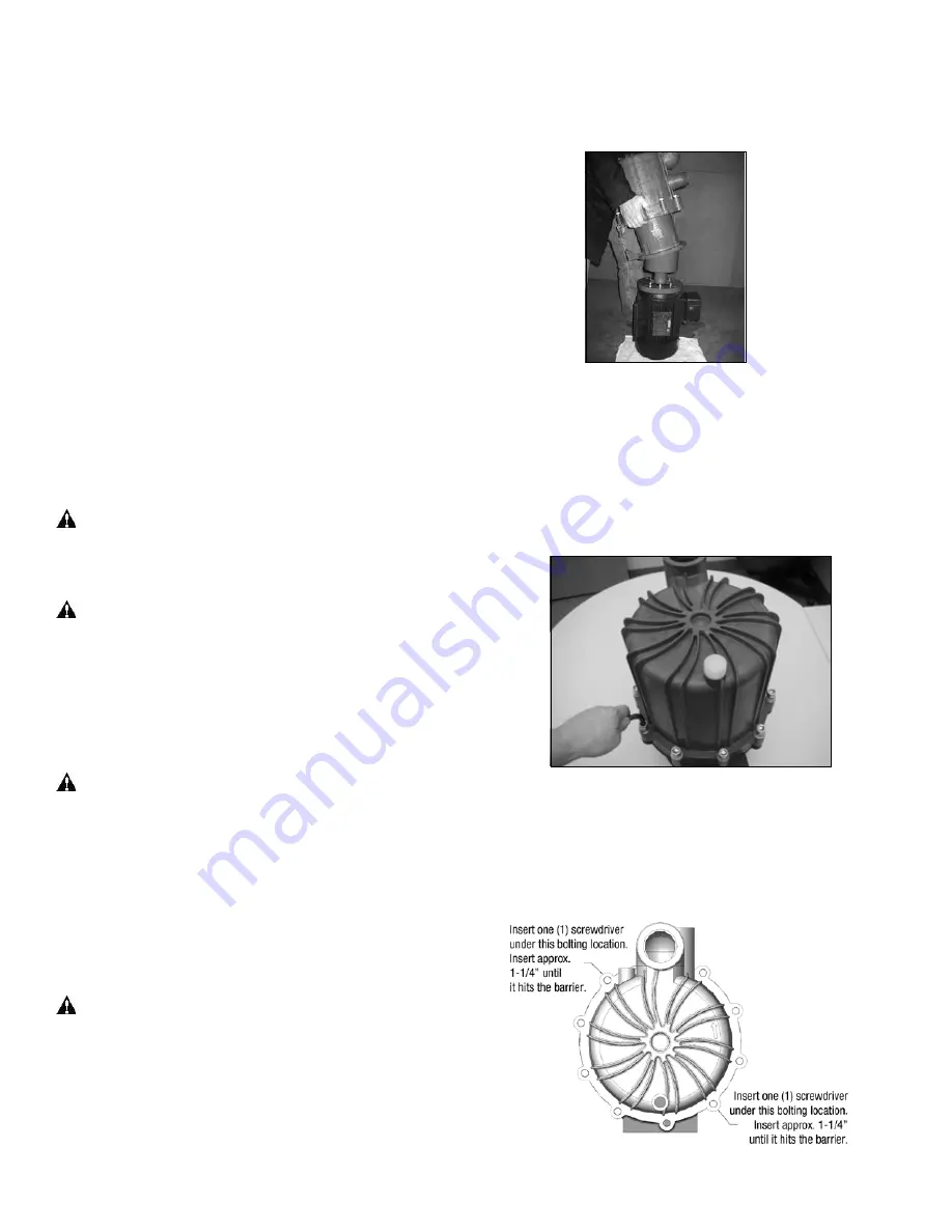
Remove the housing (item 1) by carefully inserting two flat  


head screwdrivers at the locations shown in Figure 12  Slide  


the screwdrivers in at the bolt holes between the metal mot- 


or adapter and the housing until they stop  

Figure 12

Summary of Contents for SP22 Series

Page 1: ...Assembly Installation and Operation Manual SP22 Series Self Priming Pumps...

Page 2: ...ntenance 9 Section V Disassembly 9 12 Outer Drive Replacement 11 Impeller Thrust Ring 11 Impeller Bushing 11 Impeller Disassembly 11 Reassembly 11 12 SP22 Part Number Explanation 13 Spare Parts Diagra...

Page 3: ...This pump should only be disassembled and assembled using the recommended procedures The magnetic attraction is powerful enough to rapidly pull the motor end and the wet end together Do not place fing...

Page 4: ...have silicon carbide components for best results Pumping solids may lead to increased wear NOTE While the pump is capable of being used in sump applications it is NOT a trash pump Care must be taken t...

Page 5: ...iming Liquid Volume Initial filling or refilling after maintenance of the pump housing requires 2 1 2 US gallons 9 5 liters of liquid Priming Time Priming time varies with the impeller diameter and sp...

Page 6: ...12 B5 M12 x 1 75 132 B5 M12 x 1 75 For 90 132 with B14 flange 145TC motors Install the flange item 14 on motor with pockets depressions side towards the motor face Align 4 holes in the adapter with th...

Page 7: ...o the applica tion NPSH available should be two feet 6 meters greater than NPSH required Figure 8 Figure 9 Total suction lift including pipe friction loss and cor rections for specific gravity must no...

Page 8: ...ppropriate customer supplied fittings Using the drain helps to promote superior flushing and draining results strainer must be periodically cleaned to prevent restriction Strainer hole size should be...

Page 9: ...e may be small quantities of chemicals present during inspection WARNING Magnetic force hazard This pump should only be disassembled and assembled using the recommended procedures The magnetic attract...

Page 10: ...inner volute item 6 pull back on the 3 snap fit prongs one at a time so that the hook portion falls into the channel on the inner volute See figures 15 and 16 Figure 14 Figure 15 Figure 16 9 Pull the...

Page 11: ...ut Motors steps 3 4 Impeller Thrust Ring The impeller thrust ring is located in the front of the impeller shroud and is held in place with a snap fit ridge Removal 1 Using a razor knife or side cutter...

Page 12: ...rive magnet following instructions found in Assembly Pumps without motors steps 5 8 Figure 29 Figure 30 12A in the groove in the motor adapter before installing the barrier inner volute impeller inner...

Page 13: ...odel numbers contain V have primary components molded from PVDF Base model numbers are SP22P SP22V Alternative Components Price Adders Component Base Alternative Code Bushing Carbon or PTFE T O ring V...

Page 14: ...14 25 18 26 6A 12B 13B SP22 PARTS DIAGRAM 2A 2 5 6 7A 4 8 8A 9 10 11 12 13A 14 2 2A 15 17 19 7 13 20 21 23 24 16 14A 1 3 12A 22 6B...

Page 15: ...eller 6 00 w FKM seal 107459 4 107459 5 3A impeller 5 88 w FKM seal 107459 20 107459 21 3B impeller 5 75 w FKM seal 107459 22 107459 23 3C impeller 5 63 w FKM seal 107459 24 107459 25 4 impeller 5 50...

Page 16: ...lled PTFE 106757 SiC 106757 1 9 1 Impeller Shaft Ceramic 106450 SiC 106450 1 Hastelloy C 106450 2 10 1 Housing O ring EPDM 106765 FKM 106764 11 1 Barrier 106400 2 106400 3 12 1 Motor Adapter 106414 1...

Page 17: ...01023 106499 20 4 Motor Adapter Flatwasher 106497 106500 21 1 Drive Bolt IEC Only 90 frame 105770 105771 100 112 frame 105774 105775 132 frame 106507 106508 22 1 Drive Lockwasher IEC Only 90 frame J10...

Page 18: ...4 106747 2 106747 16 106747 18 106747 20 106747 4 106747 22 PVDF 106747 1 106747 11 106747 13 106747 15 106747 3 106747 17 106747 19 106747 21 106747 5 106747 23 Thrust Ring Impeller Material 3B 3C 4...

Page 19: ...than 3 inches Closed discharge valve valve should be open Inner volute o ring chemically attacked cut brittle etc Excessive Power Consumption Head lower than rating Excessive flow Specific gravity or...

Page 20: ...is valid provided that the devices are fully assembled and no modifications are made to these devices Type of Device Centrifugal Pumps Models AC AK AV 400 500 600 800 GP 11 22 32 VKC 5 5 6 6H 7 8 10...

Reviews: