


Installation and Operation
The IPS-A223S and IPS-A511S inserts have a mounting standard
that will fit any FSR IPS series wall plates or IPS Rack Mount Frame.
Mounting screws are included for both products.
NOTE:
Do not plug the included power supply in until the cabling installation is
completed and the unit is mounted.
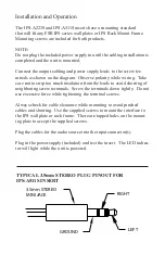
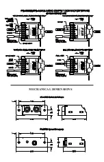
Connect the output cabling and power supply leads to the screw ter-
minals as shown on the diagram. Observe polarity while wiring. Take
care not to strip too much insulation from the leads to avoid shorting of
neighboring screw terminals. Screw the terminals down tightly. Do not
use excessive force while tightening the terminal screws.
Always check for cable clearance while mounting to avoid pinched
cables and shorting. Use the supplied screws to mount the interface to
the IPS wall plate or rack frame. There are tapped holes on the mount-
ing plate to accept the supplied screws..
Plug the cables for the audio source into the input connector(s).
Plug in the power supply (included) and test the insert. The LED indica
-
tor will light while the unit is powered.
TYPICAL 3.5mm STEREO PLUG PINOUT FOR
IPS-A511S INSERT
3.5mm STEREO
MINI JACK
RIGHT
LEFT
GROUND


