


- 4 -
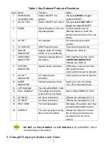
Table 1. Key External Parts and Functions
Item Name
Function
Notes
1
MSW (MAIN
CONTROL SW)
Switch ON/OFF the
system
Hard press
MSW
to toggle
system ON/OFF.
2
AC OUT SW
Switch ON/OFF AC output Hard press
AC OUT SW
to
toggle AC output ON/OFF.
3
MODE
Select Standby or On-Line
Operating Mode
Typical transfer time for
Standby Mode is 16mS. No
transfer time (0mS) for On-Line
Mode.
4
AC OUT
AC output(s)
AC socket(s) varies with
country.
5
5V USB OUT
USB Power Sources
Total current rated at 2A.
6
GAUGE
INDICATOR
Display State Of Charge
(SOC) of Li-Ion batteries
(Please see Table 2)
7
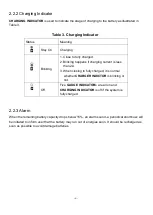
CHARGING
INDICATOR
Indicate charging state of
the battery
With a lightening mark under
CHARGING INDICATOR
.
(Please see Table 3)
8
SYSTEM
INDICATOR
System status indication
USB power outlet is synched
with system power.
Light up when power is present.
9
AC OUT
INDICATOR
AC output power
indication
Light up when power is present.
10
MODE
INDICATOR
Indicate operating mode
Light up for On-Line Mode.
Turn off for Standby Mode.
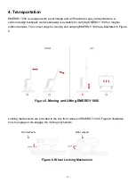
11
LIFT HANDLE
For Lifting EMERGY 1000.
12
PULL HANDLE
For pulling/ pushing the
system while on wheels.
Not for lifting EMERGY 1000.
13
AC INLET
AC Input connection
(Please see paragraph 3.2.1)
14
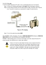
PV INLET
AC Input connection
(Please see paragraph 3.2.2)
15
HEAT SINK
For heat dissipation
Blockage of heat sink area may
impede system performance.
16
WHEELS
For carrying system along
flat or smooth surface.
Please see Figure 6 to know
the locking mechanisms are
provided in the two front
wheels.
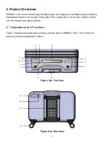
DO NOT
use
PULL HANDLE
, but
LIFT HANDLE
to lift up EMERGY 1000 to
avoid damage to the system.
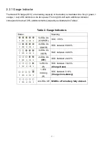
2.2 Gauge/Charging Indicators and Alarm