FRYMASTER FPHD65 SERIES GAS FRYERS
CHAPTER 7: TROUBLESHOOTING
7-5
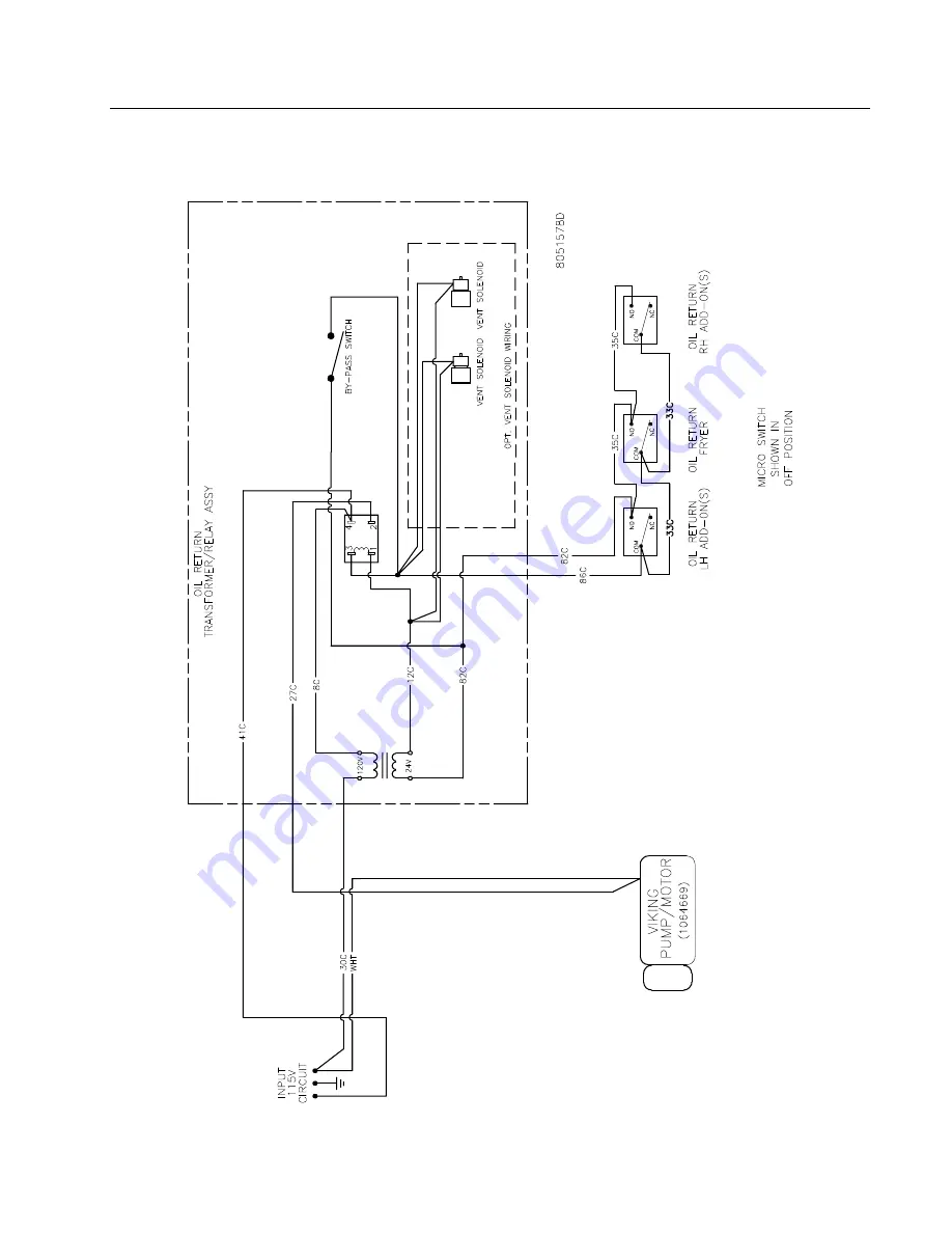
7.5 Wiring Diagram, Filter
Page 1: ...ecommends using CFESA Certified Technicians 24 Hour Service Hotline 1 800 551 8633 MAR 09 8196445 Frymaster FPHD65 Series Gas Fryers Installation Operation Manual Please read all sections of this manu...
Page 2: ...ust accept any interference received including interference that may cause undesired operation While this device is a verified Class A device it has been shown to meet Class B limits CANADA This digit...
Page 3: ...ntact with the hot oil DANGER Do not store or use gasoline or other flammable vapors and liquids in the vicinity of this or any other appliance DANGER Instructions to be followed in the event the oper...
Page 4: ...2 1 2 1 Receiving and Unpacking Equipment 2 1 2 2 General 2 2 2 3 Principles of Operation 2 3 2 4 Rating Plate 2 3 2 5 Pre Installation 2 3 2 6 Air Supply and Ventilation 2 5 2 7 Equipment Installed...
Page 5: ...eneral 5 1 5 2 Filtration Preparation 5 1 5 3 Daily Filtration Operation 5 4 5 4 Operating the Filter 5 6 6 PREVENTATIVE MAINTENANCE 6 1 6 1 General 6 1 7 TROUBLESHOOTING 7 1 7 1 General 7 1 7 2 Pilot...
Page 6: ...for the location of your nearest factory authorized service center To assist you more efficiently always provide the service technician with the model number gas type serial number and the nature of t...
Page 7: ...U S Government Printing Office Washington DC 20402 Stock No 004 000 00345 4 1 5 Safety Information Before attempting to operate your unit read the instructions in this manual thoroughly Throughout thi...
Page 8: ...the installation of gas fired appliances Qualified personnel must be experienced in such work be familiar with all gas precautions involved and have complied with all requirements of applicable nation...
Page 9: ...damage If damage is unnoticed until equipment is unpacked notify freight company or carrier immediately and file a concealed damage claim This should be done within 15 days of date of delivery Be sure...
Page 10: ...or regulations in force in the country in which the equipment is installed DANGER Building codes prohibit a fryer with its open tank of hot oil shortening from being installed beside an open flame of...
Page 11: ...s orifices DANGER Fryers MUST be connected ONLY to the gas type identified on the attached rating plate 2 5 Pre Installation DANGER No structural material on the fryer should be altered or removed to...
Page 12: ...m casters C Installation Standards 1 U S installations must meet 2 Canadian installations must meet American National Standard Institute CAN 1 B149 Installation Codes ANSI Z83 11 Canadian Gas Associat...
Page 13: ...drafts in the room D Do not place the fryer s flue outlet directly into the plenum of the hood as it will affect the gas combustion of the fryer E Never use the interior of the fryer cabinet for stora...
Page 14: ...of the filtration fryer cabinet Remove filter pan from the cabinet Uncrate fryers and remove the pallet supports Install ramps and slowly roll the fryer s off the pallets See Figure 1 2 Remove covers...
Page 15: ...he top caps Seal with hi temp silicon Two screws secure the strip at the front See Figure 6 14 Attach the flue cap connecting bracket 15 With the fryers still clamped together mount joining brackets f...
Page 16: ...aterial in the burner and gas controls will cause improper and dangerous operation NATIONAL CODE REQUIREMENTS This equipment is to be installed in compliance with the Basic Plumbing Code of the Buildi...
Page 17: ...d suitable for the gas being used and all connections must be tested with a solution of soapy water before lighting any pilots Never use matches candles or any other ignition source to check for leaks...
Page 18: ...nifold gas pressures Natural gas units normally require 4 W C and propane units normally require 11 W C gas pressure 2 Double check the arrow forged into the bottom of the regulator body which shows g...
Page 19: ...restrained by means independent of the flexible coupling or connector in order to limit the movement of the fryer Clips are located on the back panel of the fryer for the attachment of restraints 3 I...
Page 20: ...please refer to the gas valve illustration on page 3 9 Pilot Flame Adjustment Turn the pilot adjustment screw clockwise counter clockwise until the desired flame volume is achieved 3 3 2 Gas Conversi...
Page 21: ...l Electrical Code ANSI NFPA 70 latest edition DANGER This fryer is equipped with three prong grounding plugs for protection against electrical shock and must be plugged directly into a properly ground...
Page 22: ...and remove the crumb screen covering the heating tubes Ensure the screws holding the thermostat and high limit control sensing bulbs into the frypot are tight WARNING Do not bang fry baskets or other...
Page 23: ...lve then to the pilot and main burners The pilot is located high in the cabinet center at the base of the frypot WARNING Never use a match or taper to light pilot on this ignition system 1 Turn gas ON...
Page 24: ...perature and may cause injury to nearby personnel A Pour cleaning solution into the frypot and add water to the bottom OIL LEVEL line scribed in the back of the frypot B Operating thermostat equipped...
Page 25: ...y hold the entire contents of the frypot under the drain port to collect the water boil out solution Do not allow water or boil out solution to drain into the filter pan The filter pump is not designe...
Page 26: ...pieces and pack it below the heat tubes between the tubes and on top of the tubes leaving no air spaces around the tubes Do not disturb or bend the probe sensing bulbs C Press the computer on off swi...
Page 27: ...systems can be special ordered with a filter leaf assembly which eliminates the need for filter paper Both types require the use of filter powder to enhance the filtration process Photos used in the...
Page 28: ...wash the filter pan and all accessories in hot soapy water c and dry thoroughly 5 3 2Filter Unit Types FILTER PAPER AND HOLD DOWN RING Filter paper is held in place by a hold down ring Oil moves throu...
Page 29: ...it Types cont FILTER LEAF A filter leaf is a fine mesh screen which is reusable and takes the place of disposable paper Oil moves through the leaf leaving behind impurities 1 Filter pan 2 Filter leaf...
Page 30: ...e paper covers the filter pan bottom and laps two inches onto the pan wall 3 Position the hold down ring on top of the filter paper Ensure the hold down ring seals around the support grid This prevent...
Page 31: ...ter sheet Ensure the powder covers the filter paper evenly 5 Place the crumb screen in the filter pan Allow the crumb screen to rest on the top edges of the hold down ring 6 Return filter pan to cabin...
Page 32: ...damage the tubes or connectors in the pan 3 Remove the filter leaf by lifting up on the pickup tube and raising the filter leaf assembly gently out of the filter pan 4 Clean the filter leaf assembly c...
Page 33: ...s 227g of filter powder on the filter leaf Ensure the powder covers the mesh evenly 7 Replace the crumb tray in the pan after filter powder application 8 Return the filter pan to the fryer cabinet Ens...
Page 34: ...perating temperature 350 F 177 C When filtering begins the filter motor engages and oil is drawn through filter paper or a filter leaf assembly and pumped back into the frypot through oil return plumb...
Page 35: ...e sediment during filtration or oil change Clean out Rod design may vary used to dislodge heavy debris in the drain tube when needed Filter Powder Filter Paper not used in filter leaf equipped filter...
Page 36: ...less cooking oil is at operating temperature 350 F 177 C 1 Ensure the filter pan assembly is prepared as described in Section 6 2 1 Assembling the Filter and ensure fryer is turned off 2 Remove fry ba...
Page 37: ...frypot into the filter pan Drain ONLY one frypot at a time The filter pan is designed to hold the contents of one frypot only 5 After all oil has drained from the frypot into the filter pan pull the...
Page 38: ...r approximately 5 minutes process known as polishing to remove suspended particles 8 After the filter cycle is complete close the drain valve push the red handle to the left until it stops and allow t...
Page 39: ...ter pump see Step 5 above for additional reference 10 If the oil level is low add oil until the level is at the top OIL LEVEL line DO NOT OVERFILL THE FYPOT This will cause oil to splash out of the fr...
Page 40: ...at the end of frying operations each day Some food particles can spontaneously combust if left soaking in certain shortening material WARNING Do not bang fry baskets or other utensils on the fryer s j...
Page 41: ...er cabinet Ensure the hose is properly connected before proceeding 3 Open the blue handled Wand Disposal valve in the cabinet above the quick disconnect 4 Place the wand into the open frypot and activ...
Page 42: ...Store the hose wand in its designated location 5 7 Complete Filtering 1 Refill the frypot by rotating the yellow handle to open the oil return valve and activate the filter pump 2 After the frypot ref...
Page 43: ...lated to effectively clean and sanitize food contact surfaces Read the directions and precautionary statements for use Particular attention must be paid to the concentration of cleaner and the length...
Page 44: ...s transformers interface boards etc are in good condition and free from oil migration build up and other debris Inspect component box wiring and ensure all connections are tight and all wiring is in g...
Page 45: ...shortening to return to the frypot indicated by bubbles in the cooking oil shortening Return the oil return handle to the OFF position The frypot should refill in no more than 2 minutes and 30 seconds...
Page 46: ...roblems and possible solutions covered are those most commonly encountered To troubleshoot perform the test set up at the beginning of each condition Follow each step in sequence 7 2 Pilot Burner Malf...
Page 47: ...ve and replace if defective B Main burner flames are small and appear lazy shortening does not come up to temperature quickly 1 Authorized Service Agent Only Check gas pressure at the pressure tap of...
Page 48: ...ll not reach the temperature setting and or runs erratically 1 Incorrect location of sensor probe or defective temperature sensor 2 Loose wiring wire connection E Fryer shortening temperature cannot b...
Page 49: ...FRYMASTER FPHD65 SERIES GAS FRYERS CHAPTER 7 TROUBLESHOOTING 7 4 7 4 Wiring Diagram Main...
Page 50: ...FRYMASTER FPHD65 SERIES GAS FRYERS CHAPTER 7 TROUBLESHOOTING 7 5 7 5 Wiring Diagram Filter...
Page 51: ...THIS PAGE INTENTIONALLY LEFT BLANK...
Page 52: ...aster 8700 Line Avenue Shreveport Louisiana 71106 TEL 1 318 865 1711 FAX Parts 1 318 688 2200 FAX Tech Support 1 318 219 7135 PRINTED IN THE UNITED STATES SERVICE HOTLINE 1 800 551 8633 819 6445 MAR 2...