background image


Frymaster, a member of the Commercial Food Equipment Service Association, recommends 
using CFESA Certified Technicians.


24-Hour Service Hotline 1-800-551-8633


AUGUST 2005

www.frymaster.com


E-mail: 

[email protected]


*8196004*


This manual is applicable to fryers manufactured beginning 

August 2003

 with serial 

numbers beginning with 0308.  For serial numbers prior to 0308, refer to manual   
819-5184. 


 NAVY SURFACE SHIP ELECTRIC 

FRYERS 


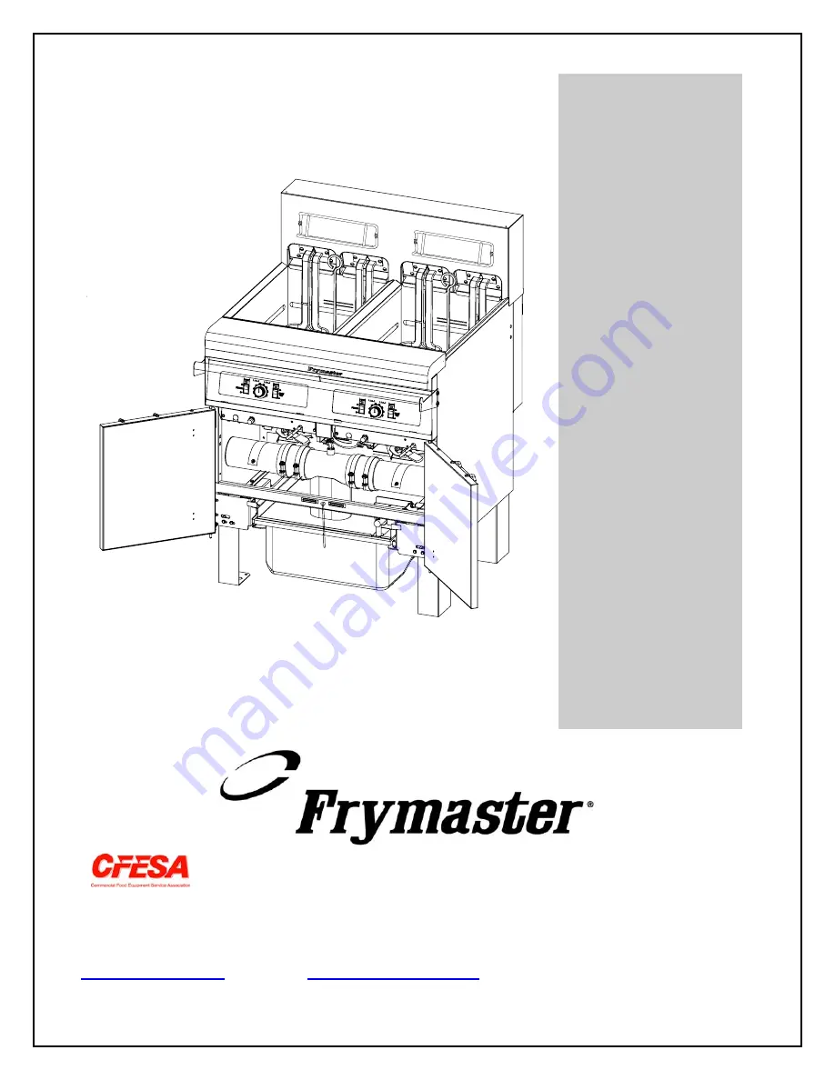
Installation, Operation, Service, and Parts Manual 

H14S

C/H1

7SC/H22

S

C Sing

le Fryers, FPPH17S

C
a

n

d

 FPH17

S

C Series Filtr

a

tion System 

Fryers 

Summary of Contents for FPH17SC Series

Page 1: ...er com E mail service frymaster com 8196004 This manual is applicable to fryers manufactured beginning August 2003 with serial numbers beginning with 0308 For serial numbers prior to 0308 refer to man...

Page 2: ...ng diagrams furnished with the equipment Wiring diagrams are located on the inside of the fryer door DANGER Do not store or use gasoline or other flammable vapors and liquids in the vicinity of this o...

Page 3: ...eived including interference that may cause undesired operation While this device is a verified Class A device it has been shown to meet the Class B limits CANADA This digital apparatus does not excee...

Page 4: ...F CONTENTS Page Chapter 1 Introduction 1 1 Chapter 2 Installation Instructions 2 1 Chapter 3 Operating Instructions 3 1 Chapter 4 Filtration Instructions 4 1 Chapter 5 Preventive Maintenance 5 1 Chapt...

Page 5: ...ore fryers 1 2 Safety Information Before attempting to operate your unit read the instructions in this manual thoroughly Throughout this manual you will find notations enclosed in double bordered boxe...

Page 6: ...uipment was carefully inspected and packed by skilled personnel before leaving the factory The freight company assumes full responsibility for safe delivery upon acceptance of the equipment 1 File Cla...

Page 7: ...o that the plug is accessible unless other means for disconnection from the power supply e g a circuit breaker is provided NOTICE If this appliance is permanently connected to fixed wiring it must be...

Page 8: ...R Observe the following precautions when connecting the fryer to an emergency cutoff system Be sure that each fryer is connected to a dedicated set of contacts in the emergency cutoff system Do not co...

Page 9: ...tline at 1 800 551 8633 2 4 After Fryers Are Anchored At the Frying Station DANGER Hot oil can cause severe burns Avoid contact Under all circumstances oil must be removed from the fryer before attemp...

Page 10: ...2 465 10 580 20 48 20 48 33 38 15 67 FRONT HANDLE Single Fryer BACK OF FRYER UNIT TYPICAL 7 098 TYPICAL 2 470 BACK OF FRYER UNIT 26 316 17 515 31 45 33 39 31 62 31 62 FRONT HANDLE 2 Fryer Battery MOUN...

Page 11: ...22 68 22 68 33 24 FRONT HANDLE 3 Fryer Battery BACK OF FRYER UNIT 7 229 47 1 31 61 31 61 35 76 35 76 7 119 2 470 17 490 33 45 Mounting Holes 625 Six Places 62 55 26 320 31 180 7 119 4 Fryer Battery F...

Page 12: ...ck the shortening around and over the elements It may be necessary to add shortening to bring the level up to the proper mark after the packed shortening has melted DANGER Never set a complete block o...

Page 13: ...s over high limit or problem in heat control circuitry 5 Thermostat Control Knob Sets desired frying temperature 6 Hi Limit Test Switch Tests high limit thermostat 7 Second Hi Limit Test Light Indicat...

Page 14: ...OCEDURE Tools Required One 0 600 F pyrometer with sensing probe or an equivalent high temperature thermometer NOTE Conduct this test when the fryer will not be needed for about one hour and when the c...

Page 15: ...and all control panel lights should have been extinguished For fryers not connected to an external shunt power supply only the fryer being tested should have been shut off 5 Place the controller power...

Page 16: ...b tray hold down ring and filter screen Clean all components with a solution of detergent and hot water then dry thoroughly The filter pan is equipped with rollers in rails much like a kitchen drawer...

Page 17: ...n of the Filter DANGER Draining and filtering of cooking oil must be accomplished with care to avoid the possibility of a serious burn caused by careless handling The oil to be filtered is at or near...

Page 18: ...Power Shower in place Hot oil will spray out of the fryer and cause injury 3 After the cooking oil has drained from the frypot turn the filter handle to the ON position to start the pump and begin th...

Page 19: ...fry vessels Banging fry baskets on the strip to dislodge shortening will distort the strip adversely affecting its fit It is designed for a tight fit and should only be removed for cleaning 4 4 Drain...

Page 20: ...cabinet with a dry clean cloth Wipe all accessible metal surfaces and components to remove accumulated oil shortening and dust Clean outside the fryer cabinet with a clean damp cloth soaked with dishw...

Page 21: ...rocess has been eliminated Also after the fryer has been in use for a period of time a hard film of caramelized vegetable oil will form on the inside of the frypot This film should be periodically rem...

Page 22: ...es Rinse the parts and accessories thoroughly with clean water and wipe dry before reinstalling 5 2 Check Calibration of Temperature Control Knob Monthly 1 After the cooking oil reaches operating temp...

Page 23: ...that the temperature and high limit probes are properly connected tightened and functioning properly and that mounting hardware and probe guards are present and properly installed Verify that compone...

Page 24: ...oil return handles in the OFF position Verify proper functioning of each oil return valve by activating the filter pump using the lever on one of the oil return handle microswitches No air bubbles sho...

Page 25: ...to ensure that it doesn t happen again If a controller malfunctions because of a poor connection check all other connections too If a fuse continues to blow find out why Always keep in mind that failu...

Page 26: ...s beyond the scope of operator troubleshooting Call FASC A Drain valve is open A This fryer is equipped with a drain safety switch that prevents the heating element from being energized if the drain v...

Page 27: ...ute controller functions correctly order a new controller If substitution of the controller does not resolve the problem the most likely cause is a failed temperature probe Fryer heats until high limi...

Page 28: ...d is beyond the scope of operator troubleshooting 6 2 3 Filtration Problems Problem Probable Causes Corrective Action A Power cord is not plugged in or circuit breaker is tripped A Verify that the pow...

Page 29: ...he Power Shower B Attempting to filter with oil or shortening that is not hot enough B In order to properly filter the oil or shortening should be at or near 350 F 177 C At temperatures lower than thi...

Page 30: ...ngage the lower tabs Then slide the bezel down to disengage the upper tabs Remove the top two screws holding the controller to the control panel frame The controller will hinge down to access the 15 p...

Page 31: ...to disengage the lower tabs Then slide the bezel down to disengage the upper tabs If applicable remove the top two screws holding the controller to the control panel frame The control panel is hinged...

Page 32: ...f more room to work is required the control panel frame and top cap assembly may be removed by removing the hex head screws that secure it to the fryer cabinet see illustration below If this option is...

Page 33: ...edge of the housing The housing can then be lifted straight up and off the fryer Lift up on the upper back panel to disengage the tabs on its upper corners from the cutouts in the fryer frame 4 Disco...

Page 34: ...d 11 In either case polarity does not matter 7 Reinstall the back panels and tilt housing to complete the installation then reverse steps 1 and 2 to return the fryer to service 7 5 Replacing a Heating...

Page 35: ...t the wires be routed through the loom to prevent chafing 1 4 2 5 3 6 1 4 2 5 3 6 7 8 9 5R 4R 6R 1R 2R 3R Pip marks Position 1 5L 4L 6L 1L 2L 3L 8 Insert the element connector into the receptacle on t...

Page 36: ...box to the floor and pull it out the front of the fryer Remove the top cover to access contactors and other components 6 After performing necessary service reverse steps 1 5 to return the fryer to ope...

Page 37: ...s 11 At the rear of the fryer unplug the C6 connector and using a pin pusher disconnect the high limit thermostat leads 12 Disconnect the oil return flexline s at the frypot end s 13 Raise the element...

Page 38: ...ter pump operation Improper screen placement is the primary cause of filtration system malfunction Whenever the complaint is the pump is running but no oil is being filtered check the installation of...

Page 39: ...e pump and allow free movement of the gears Incorrectly sized or installed paper pads will also allow food particles and sediment to pass through and clog the suction tube on the bottom of the filter...

Page 40: ...g the same procedure 5 Disconnect the two flexlines running to the oil return manifold at the rear of the fryer Remove the nut and bolt that secures the bridge to the oil return manifold Disconnect Pu...

Page 41: ...er 11 When required service has been completed reverse steps 6 12 to reinstall the bridge NOTE The black motor wires go on the top terminal the white on the bottom The pump solenoid valve wires go in...

Page 42: ...sis 3 10 OHMS Heat Contactor Coil RH R X 1 OHMS 9 of J2 Chassis 18 25 OHMS Heat Contactor Coil LH R X 1 OHMS 6 of J1 Chassis 18 25 OHMS Disconnect 15 Pin harness from the computer controller before te...

Page 43: ...7 10 Wiring Diagram System H14SC H17SC H22SC kW Single Fryers and FPH17SC kW Filter System Fryers 440 480V 60 Hz 3 3 Wire Configurations Refer to page 2 2 for power requirements FILTER POWER 8051421F...

Page 44: ...7 14 7 11 Wiring Diagram Contactor Box H14SC H17SC H22SC kW Single Fryers and FPH17SC kW Filter System Fryers 440 480V 60 Hz 3 3 Wire Configurations Refer to page 2 2 for power requirements...

Page 45: ...Dual vat oil return switch When the return valve is open the 24V circuit is closed and it activates the pump relay and drain solenoid e Optional waste oil pump switch The drain valves and oil return...

Page 46: ...0197 Cleanout Rod 27 inch 5 803 0209 Brush Frypot 6 823 1885 Connecting Strip Frypot 7 806 4041 Cover Full Vat Frypot 8 803 0132 Rack Full Vat Basket Support 9 803 0271 Basket Twin 812 1226SP Drain Ni...

Page 47: ...8 2 8 2 Cabinetry 8 2 1 Backs Control Panels Doors Handles Sides Tilt Housings Top Caps 4 8 1 2 3 7 6 5 11 12 13 10 9...

Page 48: ...shown 5 826 1351 826 1351 Nut Retainer 20 Pkg of 10 receives basket hanger thumbscrew 6 106 5205 106 5195 Top Cap Single Top cap for five station fryer shown 106 5206 106 5196 Two Station 106 5207 10...

Page 49: ...2 for cabinet sides 21 23 24 14 24 10 24 12 24 10 11 24 9 24 24 15 The 5 Station cabinet illustrated is typical of all Navy Surface Ship Electric cabinets All components used in Navy Surface Ship cabi...

Page 50: ...Stations 3 and 4 13 200 4447 Support Contactor Box Front to Rear 14 201 5369 Support Contactor Box Station 2 15 202 5369 Support Contactor Box Station 1 200 6498 Support Contactor Box Singles 16 200 4...

Page 51: ...Pkg of 5 7 816 0021 Gasket Drain Cleanout 8 810 2492 Fitting Quick Connect Straight receives Teflon vent tube 9 823 3229 Drain Outlet 10 823 3380 Drain Tube Left End 11 823 1549 Drain Tube Right End S...

Page 52: ...8 7 8 3 1 1 Euro Look Drain Tube Section and Associated Parts 8 7 7 6 6 1 3 3 4 4 5 2 2 1 See Page 8 10 for Drain Valve Detail...

Page 53: ...t 3 3 Drain Tube Right End Long 823 4639 Full Vat 3 823 4638 Dual Vat 3 4 Drain Tube Left Right Open Long 823 4641 Full Vat 3 823 4640 Dual Vat 3 5 823 4892 Drain Outlet Center Dump 6 816 0625 Sleeve...

Page 54: ...lation Drain Safety Switch 4 807 2103 Microswitch CE Straight Lever 5 901 2348 Cover Dual Vat Drain Safety Switch 6 826 1366 Nut 4 40 Keps Hex Pkg of 25 7 824 1602 Handle Full Vat Drain Valve 8 809 05...

Page 55: ...8 10 8 3 2 1 Euro Look Drain Valves and Associated Parts Units with Built In Filtration...

Page 56: ...20 Insulation Drain Safety Switch 9 810 1165 Washer Teflon Drain Valve 10 809 0196 Washer inch Flat 11 106 2671 Bracket Assembly Dual Vat Drain Safety Switch 12 810 1114 Valve 1 inch Dual Vat Drain 13...

Page 57: ...50 60 12V 20A 10 807 1612 Clamp 3 8 Connector Type Thin Screw 11 807 2181 Transformer Power 100 120V 24V 62VA 12 809 0102 Screw 8 32 x 3 8 TR SL HD ZP 13 809 0104 Screw 8 32 x TR SL HD ZP 14 809 0247...

Page 58: ...mbly 5 807 0012 Relay 18 Amp HP 24V Coil 6 826 1337 Terminal inch Push on Pkg of 5 7 807 0121 Bushing Heyco Plastic AB 625 500 8 807 1321 Holder AGC Panel Mount inch Fuse 9 807 1597 Fuse 3 Amp Slow Bl...

Page 59: ...onduit 8 807 1683 Relay 12 VDC 9 809 0096 Screw 6 32 x Bindings SL HD ZP 10 809 0102 Screw 8 32 x TR HD ZP 11 809 0250 Nut 6 32 KEPS HX ZP 12 809 0266 Screw 10 Phil TR HD ZP 13 809 0360 Screw 8 x HX W...

Page 60: ...x Right Contactor 3 200 4712 Door Contactor Box w o Hinge 4 200 2337 Bracket Contactor Box 5 807 0070 Terminal Ground Lug 6 807 2284 Contactor 24V 50 Amp Mechanical used in 14 17kW units only 7 807 22...

Page 61: ...The only difference between element assemblies for different voltage and kW ratings is the element itself Item 1 Items 21 and 22 are shown as associated parts They are not part of the element assembly...

Page 62: ...ate 7 810 0035 Hinge 8 826 1330 Screw 10 32 X inch Slotted Truss Head Pkg of 25 9 826 1376 Nut 10 32 Keps Hex Pkg of 10 10 826 1339 Bushing 375 inch Split Pkg of 10 11 816 0480 Plug 375 inch Dome 12 9...

Page 63: ...1 Contactor Box Wiring Assembly 12 Pin Full Vat C 1 BLACK GREEN YELLOW WHITE BROWN ORANGE BLACK WHITE BLACK 1 2 3 4 5 6 7 8 9 10 11 12 YELLOW RED P N 106 2477SP 8 4 5 2 Contactor Box Wiring Assemblies...

Page 64: ...bly 8 4 5 5 Main Wiring Harness P N 807 3769 15 Pin Male Connector 807 0804 Rear of Fryer C6 12 Pin Male Connector 807 0160 Contactor Box C1 4 Pin Female Connector 807 3232 Drain Safety Switches J6 J1...

Page 65: ...7 Component Box Wiring Harness 15 Pin P N 106 2506SP 8 4 5 8 Single Component Box Wiring Harness 15 Pin 8 4 5 9 Single Component Box Wiring Harness 15 Pin without Filter 8 4 5 10 Interface Board to C...

Page 66: ...8 21 8 5 Filtration System Components 8 5 1 FPH117 122 Filtration Components...

Page 67: ...x 8 5 Long 17 810 1668 Adapter Male 7 8 O D x 18 813 0022 Nipple x Close N P T B M 19 813 0098 Nipple x 6 50 N P T B M Pipe 20 813 0616 Elbow ST x NPT 90 BM 21 813 0331 Elbow W Side Outlet NPT 22 813...

Page 68: ...ltiple Battery Filtration System Components 5 6 13 14 15 7 12 11 9 12 11 10 19 NOTE Some early production units were configured this way 38 16 30 29 25 27 26 24 23 18 24 18 36 37 34 17 20 22 25 35 28...

Page 69: ...de Filter Pan Lid 11 809 0104 809 0503 Screw 8 32 X inch Slotted Truss Head 12 809 0247 Nut 8 32 Hex Keps 13 823 3879 Suction Tube 14 200 4408 Rail Left Filter 15 200 4409 Rail Right Filter 16 826 171...

Page 70: ...8 25 8 6 Frypot Assembly and Thermostat Frypot P N 823 2451SP Thermostat P N 806 7543...

Page 71: ...8 26 8 7 Oil Return System Components 23 22 21 1 2 3 4 5 11 7 8 9 10 6 12 13 14 15 16 17 18 19 20...

Page 72: ...et Handle Retainer 10 106 3349 Bracket Oil Return Microswitch 11 816 0220 Insulation Oil Return Microswitch 12 826 1359 Screw 4 40 X inch Slotted Pan Head Pkg of 25 13 826 1366 Nut 4 40 Keps Hex Pkg o...

Page 73: ...r Connectors 1 807 1068 2 Pin Female 2 807 0158 6 Pin Female 3 807 0156 9 Pin Female 5 807 0159 12 Pin Female 5 807 0875 15 Pin Female 6 807 1067 2 Pin Male 7 807 0157 6 Pin Male 8 807 0155 9 Pin Male...

Page 74: ...Shreveport Louisiana 71135 1000 Shipping Address 8700 Line Avenue Shreveport Louisiana 71106 TEL 1 318 865 1711 FAX Parts 1 318 688 2200 Tech Support 1 318 219 7135 819 6004 PRINTED IN THE UNITED STAT...

Reviews: