24G SERIES FLATBOTTOM GAS FRYERS
CHAPTER 1: SERVICE PROCEDURES
1-32
1.10.4 24GTI with Drain Safety Switch, and Boil-Out Option Enabled – 120V Non-LJS
Page 1: ...commends using CFESA Certified Technicians PRINTED IN THE USA 24 Hour Service Hotline 1 800 551 8633 DEC 2008 service frymaster com www frymaster com 8196031 24G Series Flatbottom Gas Fryers Service Parts Manual Models SCF SCFC 1824G 2424G and 1824 2424G Systems with Built In Filtration ...
Page 2: ...allation MUST conform with local codes or in absence of local codes with the National Fuel Gas Code ANSI Z223 1 The Natural Gas Installation Code CAN CGA B149 1 The Propane Installation Code CAN CGA B149 2 or The latest edition of the National Electric Code N F P A 70 NOTICE IF DURING THE WARRANTY PERIOD THE CUSTOMER USES A PART FOR THIS ENODIS EQUIPMENT OTHER THAN AN UNMODIFIED NEW OR RECYCLED PA...
Page 3: ... Class A device it has been shown to meet the Class B limits CANADA This digital apparatus does not exceed the Class A or B limits for radio noise emissions as set out by the ICES 003 standard of the Canadian Department of Communications Cet appareil numerique n emet pas de bruits radioelectriques depassany les limites de classe A et B prescrites dans la norme NMB 003 edictee par le Ministre des C...
Page 4: ...Troubleshooting and Problem Isolation Ignition Failures Improper Burner Functioning Improper Temperature Control Filtration Problems Leakage Troubleshooting Guides Pilot Burner Malfunctions Main Burner Malfunctions Indicator Lights Wiring Diagrams 24G Series Single Fryers Non CE without Boil Out Switch 24G Series Single Fryers Non CE with Boil Out Switch 24GTI with Drain Safety Switch and Boil Out...
Page 5: ...mponent Parts Control Panels Wireways and Related Components Oil Return and Suction Manifolds Filter Unit Frypot Drain and Oil Return Components Previous Style SCF Models Cabinetry Door Assemblies and Component Parts Control Panels Wireways and Related Components Oil Return and Suction Manifolds Filter Unit Frypot Drain and Oil Return Components Drain Valve and Components Wiring Connectors Pin Ter...
Page 6: ...ffers for Natural CE G20 G25 and LP CE G31 gas as indicated in the table below NON CE Altitudes of 2000 feet or less EQUIPMENT PRESSURE MODEL INPUT BTU GAS TYPE ORIFICE DRILL SIZE MM ORIFICE PART QTY MBAR INCH W C 1824 2424G 120 NAT LP 34 2 82 50 1 78 810 2051 810 2317 3 3 10 27 5 4 11 CE ONLY Altitudes of 2000 feet or less EQUIPMENT PRESSURE MODEL INPUT kW GAS TYPE ORIFICE MM ORIFICE PART QTY MBA...
Page 7: ...ve Thermatron Temperature Controller High Limit Thermostat Line Voltage Line Voltage The Pilot System 120V MELT CYCLE DISABLE 6 5 1 AC1 3 AC2 3A 2A 7 8 9 1A EXT POT PROBE 10 11 2 COM RELAY NO 12 13 NC 14 Thermocouple Pilot Coil Main Coil Gas Valve Pilot ON OFF Switch Electronic Ignition Configuration In units configured for electronic ignition an ignition module connected to an ignitor assembly re...
Page 8: ...then back ON A temperature probe monitors the temperature in the frypot When the programmed setpoint temperature is reached resistance in the probe causes the heat cycle circuitry in the controller to interrupt current flow through the heat relay This in turn interrupts the 24 VAC to the ignition module resulting in closure of the gas valve Control Options 24G Series Flatbottom gas fryers are equi...
Page 9: ...ace board at terminals 1 and 3 The temperature controls potentiometer are connected to terminals 7 8 and 9 The sensor probe circuit is connected to terminals 10 and 11 The high limit and gas valve routes through terminal 12 Terminals 2 and 13 are jumped out Terminals 5 and 6 are the melt cycle disable circuit The melt cycle is enabled unless terminals 5 and 6 are jumped out Thermatron Controller B...
Page 10: ...ing the fryer automatically opens the reset switch circuit The drain valve must be fully closed prior to resetting the safety switch 1 2 Accessing Fryers for Servicing DANGER Moving a fryer filled with cooking oil shortening may cause spilling or splattering of the hot liquid Follow the draining instructions included with the fryer before attempting to relocate a fryer for servicing NOTE Perform t...
Page 11: ...o that the opening is pointing downward 1 4 Adjusting Burner Manifold Gas Pressure WARNING This task should be performed by qualified service personnel only 1 Ensure that the gas valve knob is in the OFF position 2 Remove the pressure tap plug from the burner manifold 3 Insert the fitting for a gas pressure measuring device into the pressure tap hole 4 Place the gas valve in the ON position then p...
Page 12: ...of flame or clockwise to decrease length of flame Adjust to obtain a flame from 1 to 1 inches long 3 Reinstall the pilot adjustment screw cap 1 6 Calibrating the Thermatron Temperature Controller 1 Fill the frypot to the proper oil level line with cooking oil shortening If solid shortening is used ensure that the shortening is properly packed and melted in the frypot before proceeding 2 Ensure the...
Page 13: ...al arrows After loosening both setscrews slowly turn the dial to match the temperature reading of the thermometer Tighten each setscrew ensuring the dial does not move on the shaft during tightening 8 Allow burners to cycle on and off several times then recheck oil temperature as described in step 5 If the Thermatron dial temperature matches the thermometer temperature the controller is calibrated...
Page 14: ...nd then remove door Current production models have spring loaded door pins Disengage bottom pin from the hinge and then remove door 4 Remove the marine edge where applicable from the topcap 5 Support the control panel and remove screws securing the panel to the wireway box Remove the control panel 6 On units with switches indicator lights on the control panel mark and unplug the wiring and then re...
Page 15: ...pass through nut from the frypot Carefully remove the sensor bulb from the frypot being careful not to damage the remaining sensor bulb 10 If removing the high limit remove the screws securing it to the wireway box Mark and remove the wiring from the high limit housing High limit 11 Reverse steps to install new temperature probe or high limit If reinstalling high limit ensure the capillary tube is...
Page 16: ...e fryer from the electrical supply 2 If switches are located on front panel or control box remove the screws securing panel Do not allow the panel to hang on the switch wiring harness use some type of support 3 Depress the retaining clips see illustration below and push the switch out of the slot If there is a switch guard present retain it for installation of the replacement switch Depress clips ...
Page 17: ...of the gas valve and remove the valve 6 Remove the pipefitting from the old gas valve and install on the replacement valve using Loctite PST567 or equivalent pipe thread sealant on threads Do not apply sealant to the first two pipe threads Doing so will clog and damage the gas valve 7 Reverse steps 1 5 to install the replacement gas valve 1 7 4 Replacing the Pilot Assembly or Direct Spark Ignitor ...
Page 18: ...ning mounting screw NOTE The above procedure is applicable to fryers equipped with electronic ignition systems only 1 7 5 Removing Replacing Blower Assembly or Air Prover Switch 1 Remove back panel On systems with built in filtration use care not to damage the oil return heat tape wiring insulation when removing backs multi batteried systems after 02 03 have two piece back panels remove both to ac...
Page 19: ...essure switch with bracket Reattach sampling tube and wires removed from old switch and replace junction box cover Sail switch Remove junction box cover mark and disconnect wiring to the switch Remove screws securing the switch to the junction box and then remove the switch from the blower housing Install new switch ensuring the switch flap is correctly positioned in the blower housing Reattach wi...
Page 20: ...r tubes must be removed from the frypot firebox being inspected Remove the burner tube shield and the burner tube retainer from the burner box and set aside Lift the burner tubes up over each orifice and then pull outward to remove 3 Disconnect the pilot gas supply tube and remove the pilot assembly without electronic ignition or disconnect the sense wire and ignition cable and remove the direct s...
Page 21: ... care not to stretch or distort switch indicator light wiring if applicable If control panel is equipped with switches see Section 1 7 2 Removing Replacing Rocker Switches for detail or indicator lights mark and disconnect wiring and set control panel aside Note If equipped with indicator lights use a pin pusher to remove pins from main harness connector and then remove control panel 5 Perform Pro...
Page 22: ...hese steps will make frypot removal extremely difficult and cause possible damage to firebox components during removal 8 Remove the burner box baffle by pushing the baffle up into the burner box until the baffle studs are clear of the slots Tilt the baffle at an angle and remove it from the burner box 9 Remove screws two securing the flame spreader to the burner box Allow the spreader to drop down...
Page 23: ...ual pieces on the frypot being removed 11 Pull the frypot back and up to remove On fryers with built in filtration systems ensure the front oil return inlet is clear of the firebox front before lifting frypot out of cabinet If the Firebox Requires Replacement 12 Remove screws 12 securing the firebox to the cabinet braces arrows Lift the firebox assembly back and up to remove from cabinet Remove th...
Page 24: ...trip remains in place after installing the new frypot arrow Reverse the above steps to reassemble the fryer Use high temp silicone to re install the top assembly single fryers or joiner strips flue caps etc systems 1 8 Troubleshooting and Problem Isolation This section is intended to provide technicians with a general knowledge of the broad problem categories associated with this equipment and the...
Page 25: ...n gas supply valve is open and the circuit breaker for the fryer electrical supply is not tripped Some fryers are equipped with a fryer reset switch that must be reset each time the fryer is turned off Problems Related to the Electronic Circuits If gas and electrical power are supplied to the fryer the next most likely cause of ignition failure is a problem in the 24 VAC circuit of fryers equipped...
Page 26: ...ppropriate CE or Non CE requirements listed in the Installation and Operation manual that came with the fryer and that the pressure remains constant throughout all hours of usage Refer to Adjusting Burner Manifold Pressure in Section 1 4 if burner manifold pressure is suspected of being incorrect If popping is consistent during all hours of operation verify that the pilot is properly positioned ab...
Page 27: ... be generated for at least 11 seconds Fluctuating flame intensity is normally caused by either improper or fluctuating incoming gas pressure but may also be the result of variations in the kitchen atmosphere Verify incoming gas pressure in the same way as for popping discussed in the preceding paragraphs Variations in the kitchen atmosphere are usually caused by air conditioning and or ventilation...
Page 28: ...nected Ensure the filter paper or filter leaf is not clogged with food debris or sediment and is properly assembled If the pump motor overheats a circuit breaker in the filter circuit will trip and the motor will not start until it is reset If the pump motor does not start after pressing the circuit breaker press the red reset switch located on the rear of the motor If the pump then starts somethi...
Page 29: ...sembly partially install the housing bolts in a star pattern leaving a inch 3 18 mm gap between the cover and housing flanges Ensure there is no shortening or oil in the filter pan and that the filter pan is disconnected With the motor running slowly draw the cover in evenly tightening the housing bolts When the cover is snug on the housing tighten all bolts to 15 inch lbs 1 7 Nm ensuring that the...
Page 30: ...l return and drain fittings When installed or replaced each of these components must be sealed with Loctite PST567 sealant or equivalent to prevent leakage In very rare cases a leak may develop along one of the welded corners of the frypot When this occurs the frypot must be repaired or replaced Frypot locations indicated by arrows where potential leaks could occur ...
Page 31: ...eck that the lead from the thermocouple is tightly screwed into the pilotstat power bushing on the gas control 2 Remove end of thermocouple lead from pilotstat power unit bushing and clean with fine sandpaper Also check that bushing is clean 3 Thermocouple possibly defective millivolt output should be 12 28mv replace 4 Pilot flame may be adjusted incorrectly Adjust flame to 1 high by turning pilot...
Page 32: ...wheel preventing it from turning Clean out flue and blower wheel 2 Blower motor may have overheated and shut off This condition will correct itself when motor cools 20 minutes If problems with blower overheating persist call for service 3 If fryer is equipped with a Thermatron controller the temperature probe or the controller board may be defective Main burner flames are small and appear lazy Oil...
Page 33: ... with the respective green light switch in the following troubleshooting procedures The control panel light colors haven t changed When turning the power switch ON and resetting the safety reset switch check for the following LIGHT INDICATION PROBABLE CAUSE CORRECTIVE ACTION GREEN LIGHT POWER SWITCH IS ON GREEN LIGHT SAFETY RESET SWITCH IS OFF GREEN LIGHT CONTROL PANEL IS OFF RED LIGHT CONTROL PAN...
Page 34: ...this section depict wiring as of the date of manual publication It may not reflect design changes made to the equipment after publication Always refer to the wiring diagram affixed to the unit when actually troubleshooting this equipment 1 10 1 24G Series Single Fryers Non CE without Boil Out Switch 805 1370 E ...
Page 35: ...24G SERIES FLATBOTTOM GAS FRYERS CHAPTER 1 SERVICE PROCEDURES 1 30 1 10 2 24G Series Single Fryers Non CE with Boil Out Switch ...
Page 36: ...24G SERIES FLATBOTTOM GAS FRYERS CHAPTER 1 SERVICE PROCEDURES 1 31 1 10 3 24GTI With Drain Safety Switch and Boil Out Option Enabled LJS ...
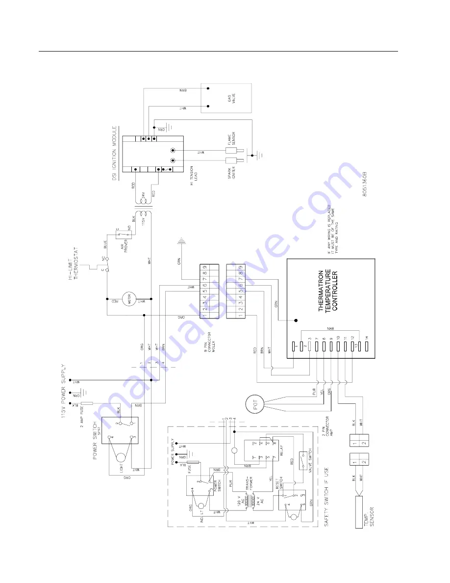
Page 37: ...24G SERIES FLATBOTTOM GAS FRYERS CHAPTER 1 SERVICE PROCEDURES 1 32 1 10 4 24GTI with Drain Safety Switch and Boil Out Option Enabled 120V Non LJS ...
Page 38: ...24G SERIES FLATBOTTOM GAS FRYERS CHAPTER 1 SERVICE PROCEDURES 1 33 1 10 5 24GTI with Drain Safety Switch and Boil Out Option Enabled 250V Non LJS ...
Page 39: ...24G SERIES FLATBOTTOM GAS FRYERS CHAPTER 1 SERVICE PROCEDURES 1 34 1 10 6 24GTI with Drain Safety Switch and Boil Out Option Disabled KFC ...
Page 40: ...24G SERIES FLATBOTTOM GAS FRYERS CHAPTER 1 SERVICE PROCEDURES 1 35 1 10 7 24GTI With Drain Safety Switch and Boil Out Option Disabled Non KFC ...
Page 41: ...VAC 50 Hz G20 G25 Nat Gas G31 Propane LP ECO Connector Assembly Threaded to Valve 24VAC to Oil Return Circuit Transformer 5 Amp Fuse 2 Pin Connector Amp 24V Thermatron Controller POT BRN BLK WHT BLU WHT BLK BLU WHT BLK 2 BLK 2 WHT 2 WHT RED RED BLK 2 WHT MOTOR BRN PUR PUR PUR BRN BRN BLU PUR BLU BLU BRN BLK WHT BRN WHT BLU 24V 230V BLK WHT PUR YLW ORG BLK WHT NC BLK GRN 1 2 1 2 1 2 3 7 8 10 9 11 1...
Page 42: ...24G SERIES FLATBOTTOM GAS FRYERS CHAPTER 1 SERVICE PROCEDURES 1 37 1 10 9 Wiring Standing Pilot SCFC Models 805 1747C ...
Page 43: ...24G SERIES FLATBOTTOM GAS FRYERS CHAPTER 1 SERVICE PROCEDURES 1 38 1 10 10 24GTI Oil Return Filter System ...
Page 44: ...ENT 1 Motor Blower Assembly 108 0471SP 120V Blower with Pressure Switch non CE 108 0470SP 230V Blower with Pressure Switch CE 2 807 3746 Switch Sail Air Prover Switch previous style fryers 3 823 3162 Duct Assembly Inlet 4 200 1428 Gate Air Flow 5 823 3166 Duct Assembly Outlet 6 200 1471 Door Outlet Duct Access Not illustrated ...
Page 45: ...24G SERIES FLATBOTTOM GAS FRYERS CHAPTER 2 PARTS LIST 2 2 2 2 Burner Manifold and Related Components 1 2 3 18 17 16 15 14 13 12 11 20 10 9 8 19 6 7 5 4 21 22 23 ...
Page 46: ...nch NPT 18 813 0845 Nipple inch NPT x 29 inch single fryers use 24 inch 813 0788 813 0729 23 Electronic Ignition Components 19 807 3556 Ignitor and Flame Sensor Assembly does not include flame sensor wire or cable 106 4580 Ignitor Bracket Flat Style After Oct 2004 210 6184 Ignitor Bracket with bends used prior to Oct 2004 20 106 1644SP Ignition Cable 21 includes Rajah connector use with sense wire...
Page 47: ...24G SERIES FLATBOTTOM GAS FRYERS CHAPTER 2 PARTS LIST 2 4 2 3 Flue Caps Top Caps and Related Components 1 2 3 5 7 8 9 10 11 12 13 14 15 16 4 6 17 ...
Page 48: ... Vat 24 18 System 823 4913 For use on 2 24 18L 3 Vat 24 18 System 823 4910 For use on 24L 18R 4 Vat 24 18 System 823 4909 For use on 24R 18L 4 Vat 24 18System 823 6881 For use on SCFC Models 2 battery 9 210 4317 Edge Strip Frypot 10 210 4313 Joiner Strip joins frypots within a system 11 210 4598 Joiner Strip joins one fryer system to another 12 823 3622 Top Assembly One Piece Short Flue 1824G use ...
Page 49: ...24G SERIES FLATBOTTOM GAS FRYERS CHAPTER 2 PARTS LIST 2 6 2 4 Common Cabinet Components SCFC Models 2 4 1 Cabinetry SCFC Models ...
Page 50: ...inch with Brake Swivel 4 hole pattern 810 0356 Caster 5 inch without Brake Swivel 4 hole patter 6 Post Rear Cabinet 220 4775 Stainless Steel or Painted 220 0404 Cold Rolled Steel 7 220 3537 Bridge Filter Pump 8 220 3790 Support Filter Pump Motor 9 106 5788 Base Filter 10 222 0980 Guide Filter Pan Left 11 221 0980 Guide Filter Pan Right 12 220 0760 Divider Frypot 13 220 4149 Stop Drain Pan 14 220 0...
Page 51: ...GAS FRYERS CHAPTER 2 PARTS LIST 2 8 2 4 2 Door Assemblies and Component Parts SCFC Models 3 4 2 1 5 ITEM PART COMPONENT 1 824 1912 Panel Door 2 220 4128 Liner Door 3 106 4067 Pin Assembly 4 810 0275 Spring 5 210 8077 Handle ...
Page 52: ...24G SERIES FLATBOTTOM GAS FRYERS CHAPTER 2 PARTS LIST 2 9 2 4 3 Control Panels Wireways and Related Components SCFC Models ...
Page 53: ...Manual Reset 200 9681 Support High Limit Thermostat 9 807 4114 Relay Latch Filter 24VAC Coil 10 807 3922 Relay Boil Out 12VDC 220 3769 Bracket Relay 11 810 2747 Spring Relay Hold Down 12 816 0220 Insulation Microswitch 13 807 2103 Microswitch Straight Lever 14 200 4719 Plate Interface Board Mounting 15 106 3729 Thermatron Board 24V Extended Melt Cycle 106 3306 Thermatron Faceplate Assembly 16 230 ...
Page 54: ...24G SERIES FLATBOTTOM GAS FRYERS CHAPTER 2 PARTS LIST 2 11 2 4 4 Oil Return and Suction Manifolds SCFC Models ...
Page 55: ... Motor 115V 60Hz gasket included 826 1270 Motor 230V 50 60Hz gasket included 816 0093 Gasket Pump Motor included with motor 15 813 0168 Elbow x NPT Street 90 16 813 0031 Bushing Hex NPT x 17 810 1668 Adapter Male OD x 18 810 1067 Flexline OD x 8 5 long 19 813 0298 Nipple x 2 0 NPT 20 813 0062 Elbow 90 21 813 0304 Bushing x Flush 22 813 0838 Nipple NPT Close 23 810 1669 Adapter Female OD x 24 810 1...
Page 56: ...with 2 casters 2 220 1145 Screen 3 810 3082 Hold Down Ring 4 823 5833 Crumb Basket 5 106 6131 Lid Filter Pan 6 810 2805 Caster 2 816 0596 O rings for filter pan pick up tube 803 0342 Filter Powder 25 pack 803 0289 Filter Paper 24 x 34 810 2800 Filter Leaf for common cabinet filter pan 816 0757 O rings for filter leaf Not illustrated ...
Page 57: ...24G SERIES FLATBOTTOM GAS FRYERS CHAPTER 2 PARTS LIST 2 14 2 4 6 Frypot Drain and Oil Return Components SCFC Models ...
Page 58: ... inch Bal Valve 810 3011 Tubing Front 810 3014 Tubing Rear 813 0165 Elbow x Street 90 813 0462 Coupling inch 813 0613 Fitting inch x inch 37 Flare 813 0614 Fitting inch x inch 37 Flare 813 0631 Elbow inch x 90 813 0649 Nipple inch NPT x 2 50 inch 813 0894 Elbow inch x inch 37 Flare 14 106 4006 Drain Valve with Microswitch 816 0211 Sleeve Red Valve Handle 807 2104 Microswitch Drain Valve Roller Lev...
Page 59: ...24G SERIES FLATBOTTOM GAS FRYERS CHAPTER 2 PARTS LIST 2 16 2 5 Previous Style SCF Models 2 5 1 Cabinetry SCF Models ...
Page 60: ...68 Kit Shim Caster contains 8 shims 900 2949 Shims Caster 14 gauge 9 200 1378 Bracket Drain Nipple Storage 10 200 4511 Hinge Universal Door for filter ready units use 200 1675 11 Back Lower Cabinet 200 4154 Units with Built in Filtration 200 4153 1824G Units without Built in Filtration for 2424G use 200 4152 12 200 4151 Back 1824G Upper Cabinet for 2424G use 200 4150 200 1607 Back 2424G One Piece ...
Page 61: ...e Pin Outer Door for 2424G use 824 1147 2 200 4548 Panel 1824G Single Pin Inner Door for 2424G use 200 4549 3 810 0180 Handle Door use 210 9739 for Euro look Handle 4 826 1343 Spring Door Hinge qty 10 5 106 4067SP Hinge Pin and Keeper Assembly Door 6 810 1105 Magnet Door 7 200 1301 Hinge Pin Door 8 824 1146SP Panel 1824G Double Pin Outer Door for 2424G use 824 1147SP 9 200 4610 Panel 1824G Double ...
Page 62: ...24G SERIES FLATBOTTOM GAS FRYERS CHAPTER 2 PARTS LIST 2 19 2 5 3 Control Panels Wireways and Related Components SCF Models ...
Page 63: ...22 807 3613 Spring Relay Retaining 23 200 1337 Bracket Oil Return Relay 24 106 1966 Socket Assembly 24V Oil Return Relay use 807 3612 for Relay Socket only 25 816 0220 Insulation Microswitch 26 807 2103 Microswitch Straight Lever 27 106 2775 Plate Assembly Microswitch Adjustment 28 200 4719 Plate Interface Board Mounting 29 826 2086 Thermatron Board 115 230V 30 210 3275 Faceplate 1824G Thermatron ...
Page 64: ...TER 2 PARTS LIST 2 21 2 5 4 Oil Return and Suction Manifolds SCF Models 30 26 10 a 29 26 26 16 29 10 a 28 27 10 a 25 18 19 20 17 16 21 2 22 23 19 10 19 18 4 3 6 7 9 5 8 24 13 1 12 15 10 a 13 14 11 33 32 31 34 35 16 106 1823SP Hose Assembly ...
Page 65: ...ve Right Oriented Flush Valves Only 106 3604 Bracket Assembly Microswitch Left Rear Flush use 106 3682 for Right 807 2103 Microswitch Straight Lever 816 0220 Insulation Microswitch 901 2348 Cover Microswitch Left Oriented Flush Valves Only 902 2348 Cover Microswitch Right Oriented Flush Valves Only 12 810 2170 Disconnect inch Male Quick 13 813 0087 Nipple inch x 1 50 inch NPT 14 813 0165 Elbow inc...
Page 66: ...692 Tubing 73 41 30 813 0452 Plug inch NPT Pipe 31 823 4547 Handle Drain Flush W A 32 816 0549 Sleeve Blue Vinyl Drain Flush Handle Cover 33 200 6135 Bracket Flush Handle Mounts to Inner Panel 34 813 0251 Nipple inch by 4 5 inch NPT 35 809 0843 Cotter Pin Not illustrated Valve stem pointing to left is left oriented Valve stem pointing to right is right oriented ...
Page 67: ...ncl Pan Filter Leaf Crumb Basket and Lid does not include item 1 2 823 3480SP Filter Pan with fittings 3 106 3675SP Filter Leaf 11 x 19 with Compression Cap Riser Connection 810 2700 Quick Disconnect inch Male SS 813 0867 Riser Standpipe Nipple inch x 6 5 inch S S 810 2760 Compression Cap with inch NPT threads 4 823 3509 Crumb Basket 5 823 3492 Lid Assembly Filter Pan 803 0002 Powder Filter 80 Ind...
Page 68: ...24G SERIES FLATBOTTOM GAS FRYERS CHAPTER 2 PARTS LIST 2 25 2 5 6 Frypot Drain and Oil Return Components SCF Models ...
Page 69: ... 9 21 04 see pg 2 22 814 0047 Sleeve Red Valve Handle 807 2104 Microswitch Drain Valve Roller Lever use 902 2348 for M S Guard 13 823 3603 Cap 1 inch NPT Pipe 14 813 0143 Nipple 1 inch x 2 inch NPT Toe 15 813 0760 Tee 1 inch x 1 inch x 1 inch NPT Drain 16 813 0686 Cap Drain Flush End 1824G Left 17 813 0165 Elbow inch x 90 NPT Street 18 200 6587 Tube 1 inch x 18 inch Drain Manifold 19 813 0632 Elbo...
Page 70: ... inch Std Port 2 106 4526 Bracket Assembly 3 816 0220 Insulation 4 807 2103 Switch Micro CE Straight Lever 5 902 2348 Cover Safety Switch11 6 826 1366 Nut 4 40 KEPS Hex Pkg of 25 7 809 0988 Washer 1 00 OD x 525 ID Teflon 8 900 2936 Retainer Nut Drain Valve 9 809 0540 Nut inch 13 Two way Hex Lock 10 210 8558 Handle 2424 Drain Valve 11 816 0211 Sleeve Plastic 1 inch Red ...
Page 71: ...r Cord Assembly 220 250V 15A 5 8 14 gauge Connectors 1 807 1068 2 Pin Female 2 807 0158 6 Pin Female 3 807 0156 9 Pin Female 4 807 0159 12 Pin Female 5 807 0875 15 Pin Female 6 807 1067 2 Pin Male 7 807 0157 6 Pin Male 8 807 0155 9 Pin Male 9 807 0160 12 Pin Male 10 807 0804 15 Pin Male 11 826 1341 Terminal Female Split Pin Pkg of 25 12 826 1342 Terminal Male Split Pin Pkg of 25 13 807 2518 Plug M...
Page 72: ...tted Pan Head 809 0839 Screw 8 32 x 75 inch Slotted Pan Head 809 0918 Screw 10 24 x inch 826 1371 Screw 8 x 50 inch Slotted Hex Head Pkg of 25 826 1374 Screw 10 inch Hex Washer Head Pkg of 25 809 0766 Nut 10 32 Hex Head 809 0823 Nut 20 Nylock 809 0247 Nut 8 32 Keps 809 0834 Nut 8 32 Hex Locknut 826 1366 Nut 4 40 Keps Pkg of 25 used to mount microswitch 809 0885 Washer Flat inch x 1 inch x 083 809 ...
Page 73: ...eturned the shortening to the frypot using a hose and wand assembly Later versions used a so called hands free plumbing assembly attached to the backsplash of the dump station The ND90 filter option was discontinued in 1996 when the fryer design was changed to incorporate the Under Fryer Filter UFF system A large number of ND90 equipped fryers were produced and Frymaster Dean continues to support ...
Page 74: ...ont NOTE The parts illustrated below are available as individual parts only See page 2 17 for the complete replacement filter assembly DRAIN LINE PARTS 11 9 10 8 7 1 2 3 41 42 44 43 40 36 37 38 22 13 23 24 39 25 26 27 28 29 31 30 13 32 22 15 33 35 34 18 26 27 4 5 6 22 13 18 18 19 17 21 20 18 12 13 13 14 15 16 ...
Page 75: ...0278 Valve inch Ball 20 813 0345 Elbow inch x 45 NPT 21 810 2321 Hose Assembly 7 inch Polishing Hose 22 810 2172 Connector inch Male Quick Disconnect 23 813 0735 Reducer inch x inch NPT Bell used with Item 24 24 810 2375 Hose Assembly inch x 32 inch 25 813 0165 Elbow inch x 90 NPT Street 26 810 2170 Connector inch Male Quick Disconnect 27 810 2173 Connector without Collar inch Female Quick Disconn...
Page 76: ...Shreveport Louisiana 71135 1000 Shipping Address 8700 Line Avenue Shreveport Louisiana 71106 TEL 1 318 865 1711 FAX Parts 1 318 688 2220 FAX Tech Support 1 318 219 7135 PRINTED IN THE UNITED STATES SERVICE HOTLINE 1 800 551 8633 819 6031 DEC 2008 ...