Frontier WR 4106 Operator'S Manual Download Page 21

ATTACHING AND DETACHING

CAUTION: Escaping fluid under pressure
can penetrate the skin causing serious
injury. Avoid the hazard by relieving
pressure before disconnecting hydraulic
or other lines. Tighten all connections
before applying pressure.
Search for leaks with a piece of
cardboard.
Protect hands and body from high
pressure fluids.

If an accident occurs, see a doctor
immediately. Any fluid injected into the
skin must be surgically removed within a
few hours or gangrene may result.
Doctors unfamiliar with this type of injury
should reference a knowledgeable
medical source, such information is
available  from Deere & Company
Medical Department in Moline, Illinois,
U.S.A.

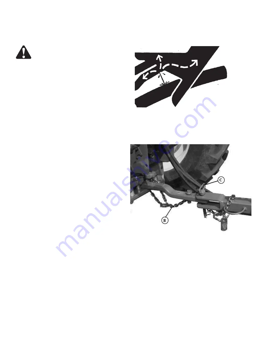
8. Disconnect hydraulic hoses (A) from tractor
receptacles.

9. Unhook safety chain (B).

10. Remove hitch pin (C).

11. Put tractor SCV levers in the neutral position.


A—Hydraulic Hose
B—Safety Chain
C—Hitch Pin

20

ATTACHING AND DETACHING

Summary of Contents for WR 4106

Page 1: ...O P E R A T O R S M A N U A L OMUS00W41 01 23 09 4106 4109 ...

Page 2: ...ection Accurately record all the numbers to help in tracing the machine should it be stolen Your dealer also needs these numbers when you order parts File the identification numbers in a secure place off the machine WARRANTY is provided as part of Frontier s support program for customers who operate and maintain their equipment as described in this manual This warranty provides you the assurance t...

Page 3: ...Hydraulic System 18 Detaching Rake from Tractor 19 TRANSPORTING Preparing Rake For Transport 21 OPERATING THE RAKE Prestarting Checks 24 Preparing Rake for Field Operation 24 Operating the Rake 26 Seting working Width 27 Adjusting Raking Wheel Height 28 Direction of travel 28 LUBRICATION AND MAINTENANCE Perform Lubrication and Maintenance 29 Observe Lubrication Symbols 29 Alternative and Synthetic...

Page 4: ...y frames 45 Assembly drawbar 46 Install hydraulic circuit 47 Assembly rake wheels 48 Install SMV Emblem 49 Install transport lights 50 FINAL INSPECTION AND LUBRICATION Final Inspection and Lubrication 51 SPECIFICATIONS High Capacity Wheel Rake 52 Record Product Identification Number 53 Tightening Flare Type Tube Fittings 53 Unified Inch Bolt and Cap Screw Torque Values 54 Metric Bolt and Cap Screw...

Page 5: ...f the signal words DANGER WARNING and CAUTION with safety messages The appropriate signal word for each message has been selected using the following guidelines DANGER Indicates an imminently hazardous situation that if not avoided will result in death or serious injury WARNING Indicates a potentially hazardous situation that if not avoided could result in death or serious injury It is also used t...

Page 6: ... Unauthorized modifications to the machine may impair the function and or safety and affect machine life If you do not understand any part of this manual and need assistance contact your Frontier dealer OPERATE RAKE SAFELY All machinery should be operated by responsible persons who have been properly instructed and delegated to do so Before each use inspect entire machine Check tightness of all ha...

Page 7: ...being operated in an unsafe manner PREPARE FOR EMERGENCIES Be prepared if a fire starts Keep a first aid kit and fire extinguisher handy Keep emergency numbers for doctors ambulance service hospital and fire department near your telephone WEAR PROTECTIVE CLOTHING Wear close fitting clothing and safety equipment appropriate to the job Operating equipment safely requires the full attention of the op...

Page 8: ... and how to do the job safely Then follow procedures and recommended equipment See your Frontier dealer for MSDS s on chemical products used with Frontier equipment USE SAFETY LIGHTS AND DEVICES Prevent collisions between other road users slow moving tractors with attachments or towed equipment and self propelled machines on public roads Frequently check for traffic from the rear especially in tur...

Page 9: ...tractor or are towed too fast can cause loss of control Consider the total weight of the equipment and its load Observe these recommended maximum road speeds or local speed limits which may be lower If towed equipment does not have brakes do not travel more than 32 km h 20 mph and do not tow loads more than 1 5 times the tractor weight If towed equipment has brakes do not travel more than 40 km h ...

Page 10: ...ine with rake wheels raised PRACTICE SAFE MAINTENANCE Understand service procedure before doing work Keep area clean and dry Never lubricate service or adjust machine while it is moving Keep hands feet and clothing from power driven parts Disengage all power and operate controls to relieve pressure Lower equipment to the ground Stop the engine Remove the key Allow machine to cool Securely support ...

Page 11: ...olvent or paint stripper remove stripper with soap and water before welding Remove solvent or paint stripper containers and other flammable material from area Allow fumes to disperse at least 15 minutes before welding or heating AVOID HEATING NEAR PRESSURIZED FLUID LINES Flammable spray can be generated by heating near pressurized fluid lines resulting in severe burns to yourself and bystanders Do...

Page 12: ... doctor immediately Any fluid injected into the skin must be surgically removed within a few hours or gangrene may result Doctors unfamiliar with this type of injury should reference a knowledgeable medical source Such information is available from Deere Company Medical Department in Moline Illinois U S A STORE ATTACHMENTS SAFELY Stored attachments such as dual wheels cage wheels and loaders can f...

Page 13: ...everage containers that may mislead someone into drinking from them Do not pour waste onto the ground down a drain or into any water source Air conditioning refrigerant escaping into the air can damage the Earth s atmosphere Government regulations may require a certified air conditioning service center to recover and recycle used air conditioning refrigerants Inquire on the proper way to recycle o...

Page 14: ...RUSTIONS ANUALS ARE AVAILABLE FROM YOUR SELLING DEALER EVER ALLOW RIDERS EEP BYSTANDERS AWAY FROM EQUIPMENT DURING OPERATION PERATE FROM TRACTOR SEAT ONLY EEP ALL SHIELDS IN PLACE AND IN GOOD CONDITION OWER EQUIPMENT TO GROUND STOP ENGINE REMOVE KEY AND SET BRAKE BEFORE DISMOUNTING TRACTOR EVER ALLOW CHILDREN OR UNTRAINED PERSONS TO OPERATE EQUIPMENT 4 ...

Page 15: ...g and operating in the field 4 Remove clevis assembly if equipped 5 If drawbar is offset turn drawbar so offset is down as illustrated The rake can be attached to any tractor having a drawbar that conforms to ASAE SAE standards of 330 to 559 mm 13 to 22 in A from the ground USING DRAWBAR SHIELD If a tractor drawbar catches and disturbs the windrow under the tractor a drawbar shield can be used See...

Page 16: ...ft links to avoid interference with rake tongue when making turns CHECKING BALLAST WHEEL SPACING AND TIRE INFLATION Provide sufficient weight to stabilize tractor when operating on hilly land or other adverse conditions See your tractor operator s manual To insure proper stability adjust ballast wheel spacing and tire inflation according to tractor operator s manual 15 PREPARING THE TRACTOR MAKING...

Page 17: ...e only the tires specified TIRE SIZE TIRE PRESSURE 5 00x15 directional 275 kPa 40 psi 2 7 Bar CHECKING WHEEL NUT TORQUE Whenever a wheel has been removed and installed check torque after one hour of operation and at 50 hour intervals Wheel nut should be tightened to 115 N m 85 lb ft 16 ...

Page 18: ...key A Hitch Pin B Quick lock Pin 6 Install hitch pin A Fasten with quick lock pin C Chain CAUTION A safety chain will help control drawn equipment should it accidentally separate from the drawbar A runaway machine could cause severe injury or death to someone Provide only enough slack in chain to permit turning Do not use safety chain for towing 7 Connect chain C to rake tongue Route chain through...

Page 19: ...uids If an accident occurs see a doctor immediately Any fluid injected into the skin must be surgically removed within a few hours or gangrene may result Doctors unfamiliar with this type of injury should reference a knowledgeable medical source Such information is available from Deere Company Medical Department in Moline Illinois U S A 1 Push tractor SCV levers in the float position 2 Connect hyd...

Page 20: ...n See Preparing Rake for Transport in the Transporting section 2 Lower rake wheels or raise rake wheels fully and lock in transport position If rake wheels are raised Remove spring clip pin from operating position A Pull short pipe B out and align pipe holes Install spring clip pin in transport position C 3 Park rake on a level surface or block ground wheels so machine cannot roll after detaching ...

Page 21: ...dent occurs see a doctor immediately Any fluid injected into the skin must be surgically removed within a few hours or gangrene may result Doctors unfamiliar with this type of injury should reference a knowledgeable medical source such information is available from Deere Company Medical Department in Moline Illinois U S A 8 Disconnect hydraulic hoses A from tractor receptacles 9 Unhook safety chai...

Page 22: ...n A is attached Provide only enough slack in chain to permit turning CAUTION Prevent collisions between other road users slow moving tractors with attachments or towed equipment and self propelled machines on public roads Frequently check for traffic from the rear especially in turns and use hand signals or turn signal lights Use headlights flashing warning lights and turn signals day and night Fo...

Page 23: ...transport position C A Pin in Operating Position B Pipe C Pin in Transport Position TRANSPORTING 22 Close the rake to the transport position following these operationssss 1 Pull the lever 1 to unhook the drawbar 2 from the regulating plate 3 use the cord with handle 4 to pull the lever from the tractor 2 Rotate the drawbar towards the main rake frame to align the head of the pivot 5 to the last ho...

Page 24: ...ertighten spring Overtightening will prevent the rake from opening and closing when needed 10 Spring A on wheel brake should be compressed 45 mm 1 25 32 in to keep wheel from wobbling If needed turn nut B one revolution to increase spring compression Repeat as necessary 23 ...

Page 25: ... loose tines bolts or missing hardware Check tire inflation pressure Correct tire pressure is 275 kPa 40 psi 2 7 Bar Check wheel nut torque Wheel nuts should be tightened to 115 N m 85 lb ft PREPARING RAKE FOR FIELD OPERATION CAUTION To prevent personal injury caused by unexpected movement Park machine on a level surface Engage tractor parking brake and or place transmission in Park Shut off tract...

Page 26: ...der or damage to opening system may occur Cylinder diameter should be 60mm 2 in with a 203 mm 8 in stroke Cylinder length when completely closed should be 463 mm 18 in 4 Move rake wheel lift rod to operating position Raise rake wheels to maximum height Remove spring clip pin A from transport position Push short pipe section into end of rear pipe Align the hole nearest washer B with the hole in rea...

Page 27: ...in Engage tractor parking brake and or place transmission in Park shut off tractor engine and remove key before servicing or making adjustments to rake Regulate ground speed according to crop condition terrain and tractor horsepower In general raking speeds at 8 11 km h 5 7 mph will produce good results A slower ground speed may be necessary for hills or rough terrain For sickle mowed crop rake in...

Page 28: ... former one just pull the lever 1 to unhook the drawbar 2 from the regulating plate 3 Use the cord with handle 4 to pull the lever from the tractor Then rotate the drawbar to align the head of the pivot 5 to one of the holes of the regulating plate 3 Release the lever to hook the drawbar to the regulating plates 3 27 Working Width 9 Wheel Rake A 0 to 6 05m 0in to 20 ft 2 in Working Width 6 Wheel R...

Page 29: ...ntity of crop being raked To adjust raking wheel height 1 Lower raking wheels 2 Make sure spring lock pin A is in operation position 3 Turn crank B clockwise to decrease ground pressure turn crank B counterclockwise to increase ground pressure 28 The rake is provided with a directional ground wheel 1 that can be set following this operation 1 Remove the pin 2 2 Rotate the directional ground wheel ...

Page 30: ...m each lubrication and maintenance illustrated in this section at the beginning of the season and at the end of the season Clean lubrication fittings before lubricating Replace lost or broken fittings immediately If a new fitting fails to take grease remove and check for failure of adjoining parts OBSERVE LUBRICATION SYMBOLS Follow hourly C intervals on grease symbols A and oil symbols B GREASE SY...

Page 31: ...in this manual apply to both conventional and synthetic oils Refined base stock products may be used if the finished lubricant meets the performance requirements GREASE Use grease based on NLGI consistency numbers and the expected air temperature range during the service interval The following greases are preferred John Deere HD POLYUREA GREASE The following greases are also recommended John Deere...

Page 32: ...nd other contamination Store containers on their side to avoid water and dirt accumulation Make certain that all containers are properly marked to identify their contents Properly dispose of all old containers and any residual lubricant they may contain EVERY 10 HOURS Check all attaching hardware every 10 hours especially during the first 50 hours of operation Make sure bolts are correctly torqued...

Page 33: ...LUBRICATION AND MAINTENANCE EVERY 50 HOURS Right Hand and Left Hand Pivoting Wheels Lift Pipe Supports Check Wheel Nut Torque Torque to 85 lb ft 115 N m 32 ...

Page 34: ...33 LUBRICATION AND MAINTENANCE Grease Drawbar Support EVERY 100 HOURS Grease Drawbar Support ...

Page 35: ...ith John Deere EP Moly or an equivalent SAE multipurpose type grease or wheel bearing grease Coat rear seal with same grease 8 Install rear bearing and seal 9 Install wheel hub front bearing washer and nut Tighten nut until a slight drag is felt when hub is turned Back nut off just enough to install cotter pin in hole in spindle 10 Install hub cap and wheel Tighten wheel hardware to 115 Nm 85 lb f...

Page 36: ...or damaged parts Check decals replace if missing or damaged Check bolts and fasteners tighten or replace as necessary Check tire pressure Inflate to 275 kPa 40 psi 2 7 Bar Check tires and rims for damage Check condition of raking wheels for loose hardware loose bearings and broken or bent tines Check hydraulic cylinders and hoses for leaks or damage 35 ...

Page 37: ... Hydraulic system inoperative Remote outlet valve not activated Open remote hydraulic outlet valve Hose from implement not properly Connect hose connected to tractor Hydraulic oil level too low in tractor Check tractor operator s manual for proper oil level 36 ...

Page 38: ...pressure Tines breaking Excessive ground speed Reduce ground speed Excessive ground pressure Reduce ground pressure Rake wheel does not turn Inadequate lubrication Lubricate wheel See Lubrication and Maintenance section Failed bearing Replace bearing Poor windrow preparation Rake wheels too high Lower rake wheels Broken or missing tines Replace tines Excessive ground speed Reduce ground speed Slow...

Page 39: ...mbly The heat can cause an increase in air pressure resulting in a tire explosion Welding can structurally weaken or deform the wheel When inflating tires use a clip on chuck and extension hose long enough to allow you to stand to one side and NOT in front of or over the tire assembly Use a safety cage if available Check wheels for low pressure cuts bubbles damaged rims or missing lug bolts and nu...

Page 40: ...SERVICE REPLACING WHEEL TINES To replace a tine 1 Remove two round head bolts A nuts clip and tine 2 Install new tine Fasten with clip round head bolts A and nuts l 39 ...

Page 41: ...ten any loose bolts nuts and hydraulic fittings 7 Repair or replace worn or broken parts 8 Paint all parts where necessary 9 Replace damaged or missing decals 10 List replacement parts needed and order them early BEGINNING OF SEASON 1 Review operator s manual and check adjustments 2 Lubricate complete machine See Lubrication and Maintenance section 3 Check air pressure in tires Correct tire pressu...

Page 42: ...ff each item after it is found satisfactory or after the correct adjustment is made Rake has been assembled correctly Check hydraulic hose and connection for oil leaks or damage Check machine for loose hardware Machine lubricated See Lubrication and Maintenance Check condition of rake wheels tines Check that all rake wheels pivot freely Check all phases of operation Check that safety chain is inst...

Page 43: ...ion and maintenance as described in the operator s manuals Daily and periodic inspections Servicing machine regularly and correctly Advise to use safety chain Make customer aware of optional equipment offered for this machine Transporting machine correctly Storing machine correctly Frontier parts and service Give operator s manual to customer and explain all operating adjustments and lubrication a...

Page 44: ...TOGETHER WITH 12X35 mm HEX BOLTS AND LOCK NUTS NOTE TIGHTEN THESE BOLTS EVENLY TO INSURE THET THE FRAMES ARE CONNECTED STRAIGHT ASSEMBLE THE ARM FOR DRAWBAR 7 ONTO THE MAIN FRAME 2 IN THE POSITION SHOWN IN THE FIGURE USE M12X30 HEX BOLTS 10 AND THE MOUNTING BRACKET FOR THE FRONT GROUND WHEEL 9 TO FASTEN THE ARM TO THE FRAME NOW PLACE A ASSEMBLY STAND 8 IN A POSITION TO SUSTAIN THE SUPPORT OF DRAWB...

Page 45: ... POSITION THE SUPPORT FORK GROUND WHEEL REAR 8 FOUR INCHES 10 cm FROM THE FLANGE OF THE FRAME NOW FASTEN THE SUPPORT 8 TO THE REAR FRAME WITH FOUR M12x140 HEX BOLTS 10 AND MOUNTING PLATE 9 MOUNT THE GROUND WHEEL REAR 12 GREASE THE UPPER PIVOT SHAFT AREA AND INSERT IT INTO THE GROUND WHEEL MOUNTING BRACKET 8 THEN SLIDE THE RING FOR REAR WHEEL SUPPORT 13 ON THE UPPER PIVOT SHAFT OF THE GROUND WHEEL ...

Page 46: ...12 LOCK NUT INSTALL THE LIFT PIPES 5 6 7 AND 8 AS SHOWN IN THE PICTURE AND SECURE THEM WITH M8X50 HEX BOLT 10 AND LOCK NUT M8 11 PUT THE LIFT PIPES IN THEIR LOCATION ON THE WING FRAMES AND LOCK WITH THE SPRING CLIP PIN 20 INSERT THE LONG FLAT HEADED PIN 19 INTO THE REAR LIFT TUBE 5 THIS PIN HAS TWO HOLES ALIGN THE HOLE NEAREST THE HEAD WITH THE HOLE IN THE LIFT TUBE AND SECURE WITH A SPRING CLIP P...

Page 47: ... ONTO THE DRAWBAR 1 AND SECURE WITH THE M24X125 PIVOT 13 AND NUT 16 ATTACH THE LEVER 9 TO THE MOUNTING EARS ON THE DRAWBAR 1 WITH HEX BOLT M8X30 AND NUT INSERT THE SPRING 12 INTO THE M25X205 PIVOT 11 AS SHOWN IN THE PICTURE AND SECURE WITH A 25X50X2 5 WASHER 23 AND A SPLIT PIN 5X40 24 SECURE THE LEVER 9 TO THE M25X205 PIVOT 11 WITH A CLEVIS 10 AND ATTACH THE CORD 7 WITH HANDLE 8 12 24 23 11 ...

Page 48: ...DE ATTACH THE CYLINDER TO THE LIFT TUBE USING THE CYLINDER MOUNTING PIN 10 ATTACH SPRING 9 TO THE TABS ON THE MOUNTING PINS TIGHTEN THE SPRING NUTS 12 TILL THE SPRING TENSIONS STRETCHED ABOUT 1 2 INCH 1 3 cm REMOVE TWO PLUGS AND INSTALL BREATHER 5 ON THE ROD END PORT AND 3 8 PIPE TREAD TO FLARE 90 DEGREE ELBOW FITTING 6 CONNECT THE HOSE 4 TO 6 INSTALL HOSE CLAMPS AND FASTEN WITH M6X25 SOCKETHEAD S...

Page 49: ...5 SLIDE THE CHAIN 10 THROUGH THE END OF THE SPRING 8 ATTACH THE RAKE WHEEL SUSPENSION SPRING TO THE TAB OF THE RAKE ARM 7 AND LIFTING PIPE TAB SECURE THE CHAIN 10 TO THE ARM TAB BY THE SHACKLE 9 NOW MOUNT ALL THE RAKE WHEELS 1 TO THE HUBS OF THE RAKE WHEEL ARMS TINE MIG CLIPS TO FRONT USE THE M10X25 HEX BOLTS 2 10X21X2 FLAT WASHERS 3 AND HEX NUTS 10 BOLT HEAD AND WASHER ON THE FRONT SIDE OF THE RA...

Page 50: ...INSTALL SMV EMBLEM 49 INSTALL SLOW MOVING VEHICLE SMV BRACKET 4 FASTEN WITH 12X102X125 U BOLT 6 AND M12 NUTS 5 INSTALL SMV EMBLEM 2 WITH M6X16 SCREWS 1 AND M6 NUTS 3 ...

Page 51: ... LIGHT 6 TO REAR OF BRACKET FASTEN WITH TWO M8X16 CAP SCREWS 8 INSTALL YELLOW LAMP 7 THROUGH BRACKET SLOT TIGHTEN NUT ATTACH WIRING HARNESS 1 TO WARNING LAMP CONNECTOR AND TAIL LAMP SOCKET POSITION THE WIRING HARNESS 1 ALONG FRAME TUBE AND FASTEN WITH THE WIRE CLIP 11 AND TIE BANDS 10 ONNECT THE SIGNAL MODULE 12 AND FASTEN WITH TIE BANDS 10 ...

Page 52: ...ust be surgically removed within a few hours or gangrene may result Doctors unfamiliar with this type of injury should reference a knowledgeable medical source Such information is available from Deere Company Medical Department in Moline Illinois U S A 1 Attach rake to tractor Refer to Attaching and Detaching section in operator s manual 2 Make sure rake has enough clearance to raise and lower 3 R...

Page 53: ...n maximum Windrow Width 6 Wheel Rake Fixed 9 Wheel Rake Fixed Overall Transport Width 6 Wheel Rake 2 55 m 8 ft 4 in 9 Wheel Rake 2 55 m 8 ft 4 in Overall Length 6 Wheel Rake 7 55m 24 ft 7 in 9 Wheel Rake 9 23m 30 ft 3 in Shipping Weight Approximate 6 Wheel Rake 450 kg 990 lb 9 Wheel Rake 585 kg 1287 lb Fold Unfold Hydraulic cylinder Adjustments Raking Width Manual Wheel Ground Pressure Manual Raki...

Page 54: ...tening in in Nm lb ft Flats Turns 3 16 7 16 8 6 1 1 6 1 4 9 16 12 9 1 1 6 5 16 5 8 16 12 1 1 6 3 8 11 16 24 18 1 1 6 1 2 7 8 46 34 1 1 6 5 8 1 62 46 1 1 6 3 4 1 1 4 102 75 3 4 1 8 7 8 1 3 8 122 90 3 4 1 8 a The torque values shown are based on lubricated connections as in reassembly TIGHTENING FLARE TYPE TUBE FITTINGS 1 Check flare and flare seat for defects that might cause leakage 2 Align tube w...

Page 55: ...SPECIFICATIONS UNIFIED INCH BOLT AND CAP SCREW TORQUE VALUES 54 ...

Page 56: ...SPECIFICATIONS METRIC BOLT AND CAP SCREW TORQUE VALUES 55 ...

Page 57: ...NOTES ...

Page 58: ...FRONTIER HIGH CAPACITY 6 WHEEL RAKE MANUFACTURED 2008 FRONTIER HIGH CAPACITY 9 WHEEL RAKE MANUFACTURED 2008 SPECIFICATIONS AND DESIGN SUBJECT TO CHANGE WITHOUT NOTICE Spare Parts 56 ...

Page 59: ...LEFT HAND SIDES ARE DETERMINED BY FACING IN THE DIRECTION OF MACHINE FORWARD TRAVEL BOX ENCLOSED ILLUSTRATIONS A KEY NUMBER SHOWN IN THE PARTS LIST IS ASSIGNED TO A BOX ENCLOSING ALL PARTS SOLD AS A SERVICE ASSEMBLY BOLT AND CAP SCREW STRENGTH IDENTIFICATION BOLTS AND CAP SCREWS REQUIRED TO HAVE HIGH STRENGTH QUALITIES EQUIVALENT TO SAE GRADE 8 ARE IDENTIFIED THROUGHOUT THIS CATALOG BY THE DESCRIP...

Page 60: ...MAIN FRAME 58 ...

Page 61: ... ZINC 2 4 12 5TNP50GZ018 JOINT LIFT TUBE l 200 1 X X 13 5TNV10AZ101 HEX CAP SCREW TE M12x35 UNI5739 ZN 12 24 14 TNV20CZ003 NUT METABLOCK M12 DIN 980 ZINCED 12 24 15 TNV80A0001 KNOB 1033 FP D 12 W COVER 1 X X 16 TNV10BZ003 SCREW TCEI M12x90 UNI 5931 ZINCED 1 X X 17 TNP50QZ014 THREADED HANDLE ZN 1 X X 18 TNV20AZ005 HEXAGONAL NUT 6S M12 UNI 5589 ZINC 1 X X 19 TNS20AZ002 PIVOT SAFETY FOR PARKING 1 X X...

Page 62: ...DRAWBAR ASSEMBLY 60 ...

Page 63: ...ED 1 X X 10 TNV50AZ001 U SHACKLE 1 4 ZN 1 X X 11 5TNC70BZ019 PIN FOR SECTOR ZINCED 1 X X 12 5TNC40AZ002 SPRING ZINCED SECTOR DRAWBAR 1 X X 13 5TNP50ZZ037 PIN ATTACHMENT DRAWBAR 1 X X 14 5TNC70BZ060 PIVOT D 32 M 30 L 180 zn 1 X X 15 5TNP70PV574 FRONT AMBER REFLECT SUPPORT 1 X X 16 TNV20BZ021 SELF LOCKING NUT NY M24x2 UNI7474 Z 3 X X 17 TNV30AZ014 WASHER 25x50x2 5 ZINCED 2 X X 18 TNV40CZ002 SPLIT PI...

Page 64: ...FRONT CRAZY WHEEL AND DIRECTIONAL WHEEL ASSEMBLY 62 ...

Page 65: ...FORK WHEEL 1 x x 14 TNV35AZ005 SPACER PIVOT G WHEEL l 64 3 x x 15 TNV60E0001 BEARING CUSC 3 x x 16 TNV35A0003 SPACER INNER WHEEL L 48 3 x x 17 TNS10AV003 HUB WHEEL SUPPORT 3 x x 18 TNV60E0004 BEARING CUSC 3 x x 19 TNV35AZ006 SPACER PIVOT WHEEL EXT L 58 3 x x 20 TNV10A0121 CAP SCREW MB 16x45 12 x x 21 TNV20BZ025 SELF CENTER NUT MB16x27x21 15 x x 22 5TNC60AS007 WHEEL 5 00x15 GREY 2 x x 5TNC60BV011 W...

Page 66: ...RIGHT HAND FINGER WHEEL 64 ...

Page 67: ...E 1 x x 9 TNV30BZ007 STEEL B WASHER 32 2x53x5 ZN 6 9 10 TNV20AZ003 HEXAGONAL NUT 6S M10 UNI 5588 ZINC 36 54 11 TNC40AZ017 SPRING FOR RAKE ARMS ZN 6 9 12 TNC45AZ001 CHAIN ZINCED PCS 23x10 7x4 5 l 506 6 9 13 TNV50AZ001 U SHACKLE 1 4 ZN 6 9 14 TNP50BV008 RAKE ARM R H W GREASER 6 9 15 TNV85A0001 BUSHING NYLON 12 18 16 TNV40CZ009 SPLIT PIN R D 5 ZN 6 9 17 TNV30A0014 STEEL BLANK WASHER M24 UNI6592 1 x x...

Page 68: ...HYDRAULIC LIFT MECHANISM 66 ...

Page 69: ...F 9 16 18 1 X X 7 TNC50BN060 CYLINDER LIFT RAKE WHEELS 2x8 1 X X 5TNC50A0101 SEALS SPARE PARTS CODES 01 X X 8 TNC30BZ007 ROD FOR CYLINDER SPRING ZINCED 1 X X 9 TNC40AZ015 SPRING LIFT CYLINDER ZN 1 X X 10 TNC70BZ011 PIVOT LIFT CYLINDER ZN 2 X X 11 TNV40CZ009 SPLIT PIN R D 5 ZN 2 X X 12 TNV20AZ003 HEXAGONAL NUT 6S M10 UNI 5588 ZINC 2 X X SEALS SPARE PARTS CODES TO ORDER THE SEALS KIT REFER TO THE PR...

Page 70: ...SMV EMBLEM 68 ...

Page 71: ...ARKS 1 5TNV10AZ002 HH M6X16 UNI 5739 ZINCED 2 X X 2 5TN1836001 SMV METAL SIGN EMBLEM 1 X X 3 5TNV20CZ006 AUTOSTOP NUT M6 UNI 7474 ZINCED 2 X X 4 5TNP50ZV351 SMV SUPPORT 1 X 5TNP50ZV354 SMV SUPPORT 1 X 5 TNV20CZ003 M12 NUT 2 X X 6 5TNV70AZ007 U BOLT M12X102X125 10 9 ZINCED 1 X X ...

Page 72: ...RIGHT HAND LIGHT 70 ...

Page 73: ...P50ZV054 LIGHTS SUPORT 1 X 4 TNC90A0002 RED REFLECTOR LABEL 1 X 5 TNC90B0004 BULBS FOR RED LIGHTS 1 X 6 TNC90D0001 RED TAIL LIGHT FIXTURE 1 X 7 TNC90D0002 AMBER LIGHT FIXTURE 1 X 8 TNV10AZ126 HH SCREW M 8x 16 UNI5739 ZINCED 2 X 9 5TNV70AZ007 U BOLT M 12x102x125 10 9 ZINCED 1 X 10 TNL05Z0004 TIE BAND 22 X 11 TNL05Z0100 WIRE CLIP 10 X 12 TNC90B0003 SIGNAL MODULE 1 X ...

Page 74: ...TO GROUND STOP ENGINE REMOVE KEY AND SET BRAKE BEFORE DISMOUNTING TRACTOR EVER ALLOW CHILDREN OR UNTRAINED PERSONS TO OPERATE EQUIPMENT 4 KEY PART NO PART NAME QTY SERIAL NO W R 4 1 0 6 W R 4 1 0 9 REMARKS 1 TNE95848 LABEL WARNING 2 X X 2 TNE95846 LABEL WARNING AVOID SERIOUS 1 2 3 TNC90A0003 YELLOW REFLECTOR 5 7 4 TNC90A0002 RED REFLECTOR 1 X X 5 5TN2451 LABEL WR 4106 2 X 6 5TN1002423JD LABEL CAUT...

Page 75: ... 65 TNV40CZ008 30 63 5TNC80AZ002 4 63 5TNV85B0001 19 61 TNS20AZ002 19 59 TNV40CZ009 16 65 5TNC90C0012 1 71 TN2411 8 72 TNS20B0001 9 63 TNV40CZ009 11 67 5TNP20BV003 23 65 TNA80683 9 72 TNS90E0001 6 63 TNV45BZ001 20 59 5TNP25AV002 1 65 TNC25A0004 6 67 TNS95AV001 22 65 TNV50AZ001 10 61 5TNP50AV420 1 59 TNC25A0010 3 67 TNV10A0121 20 63 TNV50AZ001 13 65 5TNP50AV421 2 59 TNC25E0001 1 67 TNV10AZ011 10 59...

Page 76: ...s flare type tube tightening 49 Prestarting checks 24 Flare type tube fittings tightening 49 Product identification number record 53 G R Rake wheels identifying left hand and Grease right hand 39 Extreme pressure and multipurpose 30 Rake detaching from tractor 19 Ground pressure adjusting raking wheel 28 Rake operating the 24 Rake preparing for field operation 24 Rake preparing for transpsort 21 H...

Page 77: ...t 16 Tractor drawbar positioning 14 Tractor hydraulic system attaching to 18 Transport preparing rake for 21 Transporting 21 Troubleshooting Hydraulic problems 36 Raking problems 37 Tube fittings flare type tightening 53 W Wheel ground pressure adjusting raking 28 Wheel nut torque checking 16 Wheel spacing checking 15 Wheels rake identifying left hand and right hand 39 Width adjusting windrow 27 W...

Page 78: ...NOTES ...

Page 79: ...NOTES ...

Page 80: ...PART NO OMUS00W41 ...

Reviews: