


5
EN
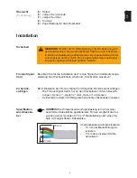
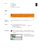
Installation
To install the Fronius Signal Card, please see the following section in the
inverter operating instructions: „Installing plug-in cards“
Fronius Signal
Card
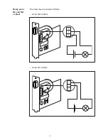
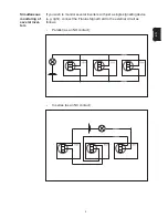
Please note
The following points should be borne in mind when installing the Fronius
Signal Card:
-
Only install Fronius Signal Cards in the slots marked „Option 1“,
„Option 2“ or „Option 3“
-
Never insert a Fronius Signal Card into a slot marked ENS
Safety
WARNING!
Danger due to grid voltage and DC voltage from solar
modules. The connection compartment should only ever be
opened by an authorised electrical engineer. The separate hou-
sing containing the power modules must only be opened by a
Fronius-trained service technician and only when in a de-ener-
gised state.
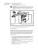
NOTE!
The effectiveness of the strain-relief device is only guaran-
teed for cables of a certain thickness. Fronius recommends a 3-pin
0.75 mm² sheathed cable or a cable of equivalent thickness.
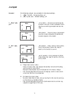
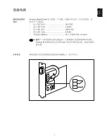
Connection
cable specifi-
cation
15 mm
5 mm
Strip the connection cable insulati-
on as follows:
-
Strip 15 mm of the sheathed
cable insulation
-
Strip 5 mm of insulation off the
individual wires
Summary of Contents for Signal Card
Page 2: ......
Page 27: ...1 Z H ...
Page 28: ...2 ...
Page 29: ...3 Z H ...
Page 30: ...4 1 4 5 8 6 7 3 2 9 ...
Page 31: ...5 Z H 15 mm 5 mm ...
Page 32: ...6 ...
Page 33: ...7 Z H ...
Page 34: ...8 ...
Page 35: ...9 Z H ...
Page 36: ...10 Buz off on Buz off on Err perm all Err perm all ...
Page 37: ...11 Z H ...
Page 38: ......


