


25
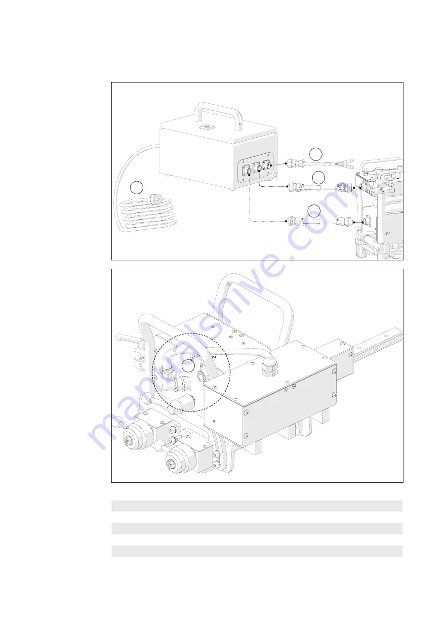
Operating elements and connections
Connections
1
5
2
3
4
(1)
Control box mains cable
(2)
Control line between welding carriage and control box
(3)
Control line between welding carriage and remote control
(4)
Connecting lead between control box and power source
(5)
Connecting lead for oscillation unit
Summary of Contents for FlexTrack 45
Page 2: ......
Page 4: ...4...
Page 7: ...7 General information...
Page 8: ...8...
Page 11: ...11 Device concept and applications continued 200 6060 m m RING application...
Page 12: ...12...
Page 13: ...13 Safety...
Page 14: ...14...
Page 18: ...18...
Page 19: ...19 Description of the welding carriage...
Page 20: ...20...
Page 36: ...36...
Page 37: ...37 Commissioning...
Page 38: ...38...
Page 52: ...52...
Page 53: ...53 Operation...
Page 54: ...54...
Page 61: ...61 Maintenance and disposal...
Page 62: ...62...
Page 67: ...67 Technical data...
Page 68: ...68...
Page 75: ...75 Spare parts circuit diagram...
Page 76: ...76...
Page 82: ...82 48 0005 1854 48 0005 1816 48 0005 1853 Remote control Item no 8 046 036...
Page 83: ...83 48 0005 1752 FTH 18 D16 25 Item no 48 0005 1752 FTH 21 Item no 48 0005 1777 48 0005 1777...
Page 85: ...85 Circuit diagram...
Page 86: ...86...
Page 87: ...87...
Page 88: ...FCP 600 II Spare parts recommendation Mechanical spare parts D...
Page 90: ...FCP 600 II Spare parts recommendation Mechanical spare parts D...