


Fristam Pumps
8
• Keep suction lines as short and direct as possible.
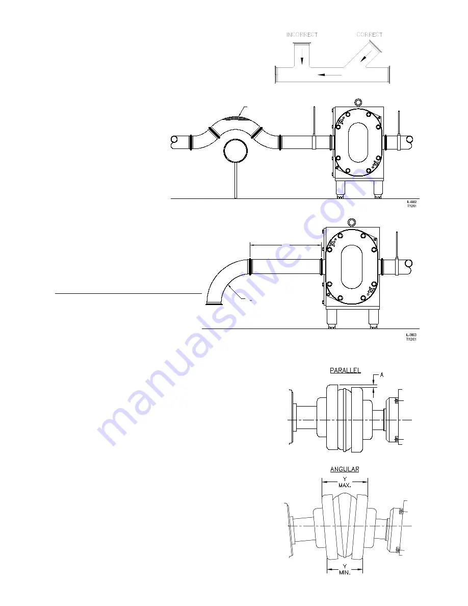
• Avoid abrupt transitions in the piping systems (Figure 4).
• Avoid the formation of air pockets in the piping (Figure 5).
• Ensure that the NPSH available in the system is greater
than NPSH required by the
pump.
• Avoid abrupt closure of shut-
off valves, this may cause
hydraulic shock which can
cause severe damage to the
pump and system.
• Avoid elbows in the suction
line if possible. When neces-
sary they should be located
5 pipe diameters away from
the pump inlet and have a
bend radius greater then pipe diam-
eters (Figure 6).
•
Install a relief valve on the discharge
side of the pump with a bypass loop
back to the suction side to ensure that
the pump cannot be over-pressurized.
A
LIgNMENT
In most cases, the pump will be shipped
with a drive unit mounted on a com-
mon baseplate. The drive and pump
are aligned at the factory; however, this
alignment should be checked after instal-
lation (Figure 7). Misalignment between the pump and drive can result in premature bearing failure or
other damage. If the pump is not shipped with a drive unit, use a flexible coupling between the pump
and drive unit. Align the pump and drive unit according to the
coupling requirements.
C
hECKINg
ALIgNMENT
Remove the wire ring from the coupling sleeve and let it hang
between the sleeve and one of the flanges.
To check the parallel alignment place a straight edge across the
two coupling flanges and measure the maximum offset at various
points around the periphery of the coupling without rotating the
coupling. If the maximum offset exceeds the figure shown under
“Parallel” in Table A1 (page 53), realign the shafts.
Check the angular alignment with a micrometer or caliper. Mea-
sure from the outside of one flange to the outside of the other
(“Y”) at intervals around the periphery of the coupling. Deter-
mine the maximum and minimum dimensions without rotating
the coupling. The difference between the maximum and mini-
mum must not exceed the figure given under “Angular” in Table
A1 (page 53). If a correction is necessary, be sure to recheck the
parallel alignment.
Reinstall the wire ring on the O.D. of the coupling sleeve.
5D
R>2D
Figure 6
AIR
Figure 5
Figure 4
Figure 7