


11
6
Installation
6.1
Safety Instructions
Falling or Unsecured Parts
Severe crush injuries.
►
Always wear gloves when performing installation-related
work.
Incomplete, Unstable Installation
Severe crush injuries, material damage.
►
Tighten screws to the specified tightening torque; see
Chapter 11.1.1, "Tightening Torques for Screws," page 28
.
►
Use a torque wrench or an impact driver with adjustable
torque.
Swinging During Adjustment of Spherical Cap Feet
Material damage to system and pump.
►
Use spherical cap base plates.
6.2
Installation Location
For standard pumps, the installation location must meet the fol-
lowing requirements:
– Nonexplosive atmosphere
– Dust-free environment
– Ambient temperature: –20°C to +40°C
– Values for moisture and salt contents in ambient air as given
in the motor supplier documentation in the attached docu-
ments
– Foundation sized adequately for the pump weight
– Horizontal and level installation surface, adequate installa-
tion surface strength for pump mass
– Installation clearances as given in the motor supplier docu-
mentation
– Adequate clearance for maintenance work
– Adequate air supply for motor cooling
6.3
Reduction of Sound and Vibration
6.3.1
Primary Measures
– Operate the pump in the optimum working range.
►
Operate the pump without cavitation (see
"Installation of Pipes," page 11
).
– Decouple the suction and discharge lines from vibrations.
►
Support lines.
►
Align lines.
►
Install vibration dampers.
6.3.2
Secondary Measures
►
Take structural measures such as the following:
– Acoustic paneling
– Enclosure in housing
6.4
Pump Fixation
6.4.1
Pump With Base Frame
►
Screw the pump on the base frame to the foundation.
6.4.2
Pump With Base Frame on Spherical Cap Bearings
(Optional)
►
Set up the pump on the spherical cap bearings and align.
6.4.3
Carriage (Optional)
1. Set up the pump at the installation location. Lock the locks
on the rollers (if present) or secure the carriage with chocks.
2. Ground the carriage to dissipate electrostatic charge.
3. Position hose line to ensure that it cannot be damaged.
6.5
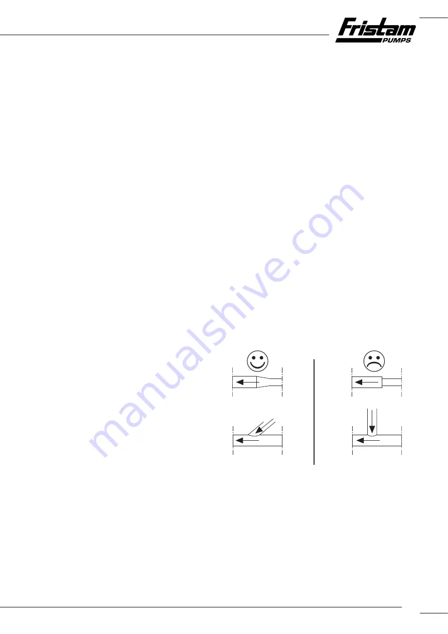
Installation of Pipes
Lay and connect pipes as follows:
►
Keep the pipe resistance as low as possible: Avoid unneces-
sary installation of valves, elbows, and abrupt pipe transi-
tions.
Fig. 11
Pipe transitions
►
Design pipe cross section so that no unnecessary pressure
losses or cavitation occurs in the suction and inlet areas.
►
Install a shut-off valve in the discharge line.
►
Design the suction lines to be as short as possible.
►
Install the suction lines in horizontal position or at a con-
stant dropping angle towards the pump unit. Rule out the
possibility of air pockets and dips in the pipes.
Summary of Contents for FKL 15
Page 32: ... FKL PUMP SERIES 32 940 Key 941 Woodruff key 950 spring Part Number Name ...
Page 37: ...37 ...
Page 38: ... FKL PUMP SERIES 38 ...
Page 39: ...39 ...