background image

Summary of Contents for FPEF4085KFD

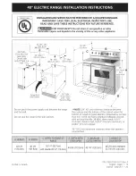
Page 1: ...62 2cm Max D Do not pinch the power supply cord between the range and the wall Do not seal the range to the side cabinets NOTE 24 61 cm minimum clearance between the cooktop and the bottom of the cabinet when the bottom of wood or metal cabinet is protected by not less than 1 4 0 64 cm flame retardant millboard covered with not lessthan No 28 MSG sheet metal 0 01 5 0 4 ram stainless steel 0 024 0 ...

Page 2: ...1982 Manufactured Home Sites Communities and Setups ANSI Z225 1 NFPA 501A latest edition or with local codes Make sure the wall coverings around the range can withstand the heat generated by the range Before installing the range in an area covered with linoleum or any other synthetic floor covering make sure the floor covering can withstand heat at least 90 F 32 C above room temperature without sh...

Page 3: ... on end of wires must be either closed loop or open spade lug with upturned ends Cord must have strain relief clamp Do not loosen the nuts which secure the factory installed range wiring to terminal block while connecting range Electrical failure or loss of electrical connection may occur NOTE Range is shipped from factory with 1 1 8 dia hole as shown in figure 3 If a larger hole is required punch...

Page 4: ...the lower end of the rear wire cover access cover upward to expose range terminal connection block see figure 2 2 Remove the grounding strap from the terminal block and from the appliance frame 3 Using the nuts supplied with the literature package connect the ground wire green of the copper power supply cord to the frame of the appliance with the ground screw using the hole in the frame where the ...

Page 5: ...e from Residence W _Ji_ _ _ i__re _ _ X_ _rCeks m Green U L listed Conduit or BareCopper Connector or CSA Wire Cablefrom listed Appliance NOTE Be sure to remove the supplied grounding strap Figure 5 3 Wire Grounded Neutral Electrical System Example Junction Box Where local codes DO NOT permit connecting the appliance grounding conductor to the neutral white wire or if connecting to 4 wire electric...

Page 6: ... wall is present on the left side of range allow a minimum of 2 3 4 7 cm to open the auxiliary door Center Line of Range I Follow instructions for the type of installation you have Figure 8 If range will be installed with a cabinet on both sides draw a center line on the floor between the cabinets see figure 8 If back of range will not be flush with the wall the location of the outlet may not allo...

Page 7: ...t to CONV BAKE ROAST at 350 177 C both elements cycle on and off alternately and the convection fan will turn The convection fan will stop turning when the oven door is opened during convection baking or roasting When All Hookups are Complete Make sure all controls are left in the OFFposition Before You Call for Service Read the Avoid Service Checklist and operating instructions in your Owner s Gu...

Page 8: ...p device has been installed to floor or wall Ensure the anti tip device is re engaged to floor or wall when the range is moved Do not operate the range without the anti tip device in place and engaged Failure to follow these instructions can result in death or serious burns to children and adults A Locate the Bracket Using the Template Locate the bracket position by placing the template on the flo...

Page 9: ...l on the oven rack Take 2 readings with the spirit level placed diagonally take a reading in one direction and then in the other direction Level the range if necessary by adjusting the leveling legs Slide Anti Tip Bracket range back Range _ _ Leveling Leg _ Anti Tip __ Bracket To check if the anti tip bracket is installed properly use both arms and grasp the rear edge of range back Carefully attem...

Page 10: ...10 ...

Page 11: ...qo pellizque el cordOn electrico entre la estufa y la pared qo selle la estufa a los armarios de lado D NOTA Un espacio m nimo de 24 61 cm entre la superficie de la estufa y el fondo del armario cuando el fondo del armario de madera o metal est 1 protegido pot no menos de 1 4 0 64 cm de madera resistente al fuego cubierta por una I_imina met_ilica de MSG nOmero 28 0 015 0 4 mm de acero inoxidable ...

Page 12: ...on los codigos locales Asegurese de que el material que recubre las paredes alrededor de la estufa pueda resistir el calor generado pot la estufa Antes de instalar la estufa en un _rea cuyo piso este recubierto con lin61eo u otto tipo de piso sintetico asegurese de que estos puedan resistir una temperatura de pot Io menos 90 F sobre la temperatura ambiental sin provocar encogimiento deformaci6n o ...

Page 13: ... correa de aterrizaje del marco y corte el otro extremo cerca de la terminal de neutral Conecte el electrodom6stico de la forma usual NOTA La cocina corrediza el_ctrica viene de fabrica con un agujero de di_imetro 1 1 8 2 9 cm come se muestra en la figura 4 Si un agujero mas largo est 1 necesario retire la arandela de la pre cortada F__ El riesgo de fuego o de choque el6ctrico puede aparecer si us...

Page 14: ...a para tener acceso cubierta de acceso al bloque de conexi6n del borne terminal vea figura 2 2 Retire la correa de la base del bloque terminal y del armaz6n del electrodom stico Retenga el tornillo de la base 3 Utilizar los tuercas suministraron en el paquete de la literatura para conectar el alambre de tierra verde del cable de bronce del suministro el_ctrico al armaz6n del electrodom stico con e...

Page 15: ...ciOn Alambre neutro blanco _ d rojos _ b_ _ Alambre _ T _ desnudos overdes Cable de la estufa NOTA Aseg0rese de quitar la banda de puesta a tierra provista Alambres negros _ Caja de empalmes J Alambre blanco Conductor de uni6n listado UL listado CSA Figura 5 Sistema El_ctrico a 3 Alambres Neutral puesta a tierra Ejemplo Caja de empalmes Donde los c6digos locales NO permitan conectar el conductor d...

Page 16: ...sera instalada junta contra un armarJo mueva la estufa a su posiciOn final Marque el piso pot los dos lados de la estufa Si la parte trasera de la estufa no estara a ras con la pared la ubicaciOn del tomacorriente puede que no permita que la estufa se pegue a ras con la pared marque en el pi5o donde el borde trasero de la estufa estar Ponga el patron en el piso y alinee Io5 lado5 del patron con la...

Page 17: ...ciOn Lista de control de averfas en su Manual del Usuario Esto le podr_i ahorrar tiempo y gastos Esta lista incluye ocurrencias comunes que no son el resultado de defectos de materiales o fabricacion de este artefacto Lea la garant a y la informacion sobre el servicio en su Manual del Usuario para obtener el n0mero de telefono gratuito y la direccion del servicio Pot favor Ilame o escriba si tiene...

Page 18: ...illos al suelo asegurase que no atraviesen la instalaci6n el_ctrica o de fontanerfa _r_ Riesgo de voicamiento Un nino o adulto puede volcar la estufa y acabar muerto Verifique que se haya instalado el dispositivo antivuelco en el piso o en la pared Asegurese de que el dispositivo antivuelco se haya reacoplado cuando mueva la estufa sobre el piso o a la pared No utilice la estufa sin el dispositivo...

Page 19: ...mo Tome minimo 2 lecturas con el nivel coloque el nivel en diagonal para que la cocina este nivelada de atrcis hacia adelante si es necesario ajuste las patas niveladoras Deslice Fijadones de la anti inclinaci6n estufa Tornillo _k__ _ nivelador _ _ _i _1 de la _ estufa __ Para verificar si la fijaciones de anti inclinacion estci instalado correctamente sostenga el borde trasero de la parte trasera...

Page 20: ...20 ...

Reviews: