42
PB
OPERATION
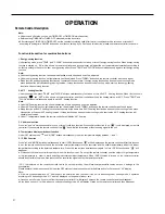
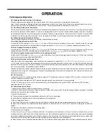
36k Sequence of Operation
1. Temperature Parameters
Indoor preset temperature (Tpreset)
Indoor ambient temperature (Tamb.)
2. Basic Functions
Once energized, in no case should the compressor be restarted within less than 3 minutes. In the situation that memory functionis
lag; if the compressor is in operation before de-energization, the compressor will be started with a 3-minute lag; and once started, the
compressor will not be stopped within 6 minutes regardless of changes in room temperature;
(1) Cooling Mode
①
Working conditions and process of cooling
When T
amb. ≥
Tpreset, the unit will enter cooling operation, in which case the indoor fan, the outdoor fan and the compressor will work and
the indoor fan will run at preset speed.
When Tamb.
≤
Tpreset -3.6°F, the compressor will stop, the outdoor fan will stop with a time lag of 60s, and the indoor fan will run at preset
speed.
When Tpreset-3.6°F < Tamb.< 1.8°F, the unit will remain at its previous state.
Under this mode, the four-way valve will be de-energized and temperature can be set within a range from 61°F~86°F. If the compressor is
shut down for some reason, the indoor fan and the swing device will operate at original state.
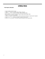
②
Protection
Run
Stop
Antifreeze protection
Under cooling and dehumidifying mode, 6 minutes after the compressor is started:
If T
evap ≤
35.6°F, the compressor will operate at reduced frequency.
If Tevap
≤
30.2°F is detected for durative 3 minutes, the compressor will stop, and after 60 seconds, the outdoor fan will stop;and under
cooling mode, the indoor fan and the swing motor will remain at the original state.
If T
evap. ≥
42.8°F and the compressor has remained at OFF for at least 3 minutes, the compressor will resume its original operation state.
Total current up and frequency down protection
If I
total
≤
16A, frequency rise will be allowed; if I
total
≥
17A, frequency rise will not be allowed; if I
total
≥
18A, the compressor will run at reduced
frequency; and if I
total
≥ 20A, the compressor will stop and the out
door fan will stop with a time lag of 60s.
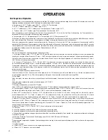
(2) Dehumidifying Mode
①
Working conditions and process of dehumidifying.
If Tamb. > 1.8°F, the unit will enter cooling and dehumidifying mode, in which case the compressor and the outdoor fan will
operate and the indoor fan will run at low speed.
If Tpreset -3.6°F
≤
T
amb. ≤
1.8°F, the compressor remains at its original operation state.
If Tamb.< Tpreset-3.6°F , the compressor will stop, the outdoor fan will stop with a time lag of 60s, and the indoor fan will
operate at low speed.
②
Protection
Protection is the same as that under the cooling mode.
60-second blow at low speed.
If 3.6°F < Tamb. < 9°F, the unit will maintain its original operating status.
(3) Heating Mode
①
Working conditions and process of heating
If Tamb.
≤
3.6°F, the unit enters heating mode, in which case the four-way valve, the compressor and the outdoor fan will operate
simultaneously, and the indoor fan will run at preset speed in the condition of preset cold air prevention.
If Tamb.
≥
9°F, the compressor will stop, the outdoor fan will stop with a time lag of 60s, and the indoor fan will stop after
Under this mode, the four-way valve is energized and temperature can be set within a range of 61°F~86°F. The operating symbol, the
heating symbol and preset temperature are revealed on the display.
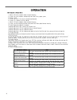
②
Condition and process of defrost
Tpreset
T3˚F
Compressor
Outdoor fan
Indoor fan
Tamb.
Stop cooling
Start cooling
Original working state
≥
6 min.
≥
3 min.
≥
6 min.
Set fan speed
without a 3 minute
Summary of Contents for FSHW091
Page 8: ...8 INTRODUCTION FSHSW09A1A FSHSW12A1A Figure 102 Indoor Units FSHSW18A3A FSHSW24A3A FSHSW36A3A ...
Page 47: ...47 INSTALLATION ...
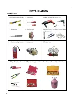
Page 48: ...48 INSTALLATION Installation Tools ...
Page 72: ...72 WIRED CONTROLLER Display ...
Page 122: ...122 TROUBLESHOOTING Malfunction of IDUFanMotorU8 Service Manual No Start End ...
Page 146: ...146 WIRING DIAGRAMS Figure 8054 9 12KOutdoorUnitWiringDiagrams 60000706067401 3 2 N 1 C3 C4 ...
Page 158: ...158 FIgure 906 PARTS CATALOG 9KOutdoorUnit 28 27 29 31 30 32 ...
Page 160: ...160 PARTS CATALOG 12k OutdoorUnit 28 27 29 31 30 32 FIgure 907 ...

