


Rittal Liquid Cooling Package
39
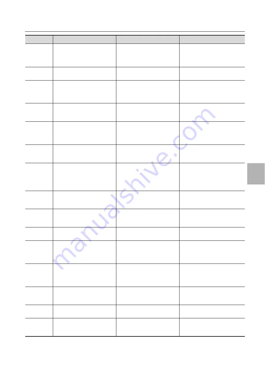
8 Troubleshooting
8
ALC01
Alarms ALC01
Position: ID2
Compressor 1 overload or invert-
er alarm
High inlet temperature, high heat
load, incorrect pipework, incor-
rect wiring.
Check operating conditions as per
compressor specifications, check
device limits, check pipework and
wiring.
ALC03
Alarms ALC03
Envelope alarm zone
Operating conditions outside of
compressor specifications.
Check operating conditions as per
compressor specifications.
ALC04
Alarms ALC04
Compressor start failure
(temp.:/max.:)
Inadequate pressure difference
during device startup, excess cur-
rent or missing phase on inverter,
blocked inverter.
Check operating conditions as per
compressor specifications, check
device limits, check error codes in
inverter manual.
ALC05
Alarms ALC05
High discharge gas temperature
High inlet temperature, high heat
load, incorrect pipework.
Check operating conditions as per
compressor specifications, check
device limits, check pipework.
ALC06
Alarms ALC06
Low pressure differential (insuff.
lubrication)
Operating conditions outside of
compressor specifications or de-
vice limits, blocked compressor,
incorrect wiring.
Check operating conditions as per
compressor specifications, check
device limits, check wiring.
ALF01
Alarms ALF01
Position: ID1
Fan overload
Incorrect wiring.
Check wiring against circuit dia-
gram.
ALD02
Alarms ALD02
Probe S1:
Probe S2:
Probe S3:
Probe S4:
Sensor failure or sensor not cor-
rectly connected.
Check the connection on the moth-
erboard or replace the sensor.
ALD03
Alarms ALD03
EEV motor error
Incorrect or missing wiring be-
tween motherboard and valve
motor.
Check the connection on the moth-
erboard or replace on the valve mo-
tor.
ALD04
Alarms ALD04
Low superheat (LowSH)
Incorrect coolant filling, insuffi-
cient heat load, insufficient fan
speed.
Check device limits, check coolant
volume, check fan speed.
ALD05
Alarms ALD05
Low suction temperature
Cf. ALD04 and ALD06.
Cf. ALD04 and ALD06.
ALD06
Alarms ALD06
Low evaporation temperature
(LOP)
Incorrect coolant filling, insuffi-
cient coolant volume, blocked
coolant lines, thermostatic valve
closed.
Check coolant volume, check lines
for leaks, check thermostatic valve.
ALD07
Alarms ALD07
High evaporation temperature
(HOP)
High inlet temperature, incorrect
PID valve parameter.
Check valve PID parameters, alarm
delay, raise the MOP limit (max.
25°C) if condenser ambient tem-
perature is max. 35°C.
ALD08
Alarms ALD08
High condensing temperature
(HiTcond)
High ambient temperature, incor-
rect coolant filling, defective fan
on condenser.
Check device limits, check coolant
volume, check fan on condenser.
ALD09
Alarms ALD09
Driver offline
Cf. inverter manual.
Cf. inverter manual.
ALL01
Alarms ALL01
Power+ offline
Wrong communication between
the driver and the motherboard.
Check the MODbus connection ca-
ble; check the communication pa-
rameters.
Alarm code
Display
Possible cause
Possible solution


