


7 Operation
7
28
Rittal Liquid Cooling Package
7
Operation
This section describes operation of the LCP DX using
the control and display devices directly on the unit itself.
Using the built-in pCO Web card, it is also possible to
access the unit via a network connection (see sec-
tion 7.13 "Configure the pCO Web card" and section 14
"SNMP card").
7.1
Control and display components
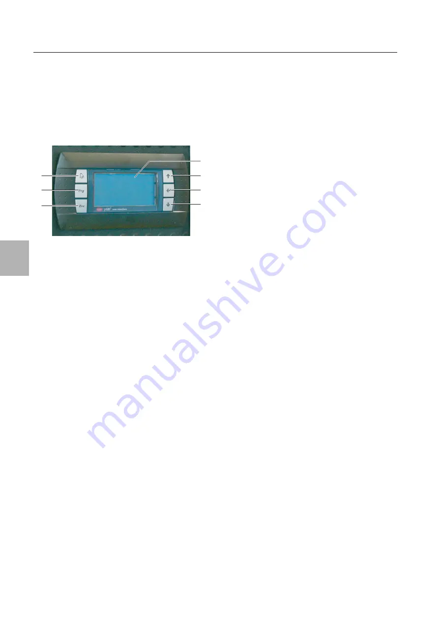
Fig. 28:
Control and display components
Key
1
Display
2
"Up" button
3
"Return" button
4
"Down" button
5
"Esc" button
6
"Prg" button
7
"Alarm" button
7.2
Switching the LCP DX on and off
7.2.1
Switching on the LCP DX and the external
condenser
Once both the LCP DX and the condenser are electrical-
ly connected and switched on at their respective master
switches, carry out the following two steps:
If you wish to switch the LCP DX on and off remotely:
In the electronics box, remove the jumper between the
two terminals 24 and 27 ("Remote On-Off") and con-
nect a floating remote switch (normally open contact)
(fig. 25, item 3).
If the two terminals are not jumpered, the status mes-
sage "Din-Off" will appear in the display.
Change the status of the device in the "On/Off Unit"
menu from "Off" to "On" (see section 7.6 "Menu level
A "On/Off Unit"").
7.2.2
Switching off the LCP DX and the external
condenser
To switch off the LCP DX and the condenser, proceed
as follows:
Change the status of the device in the "On/Off Unit"
menu from "On" to "Off" (see section 7.6 "Menu level
A "On/Off Unit"").
Switch off the LCP DX and the condenser at their re-
spective master switches.
7.2.3
Switching off in an emergency
To switch off the LCP DX and the condenser, proceed
as follows:
Switch off the LCP DX and the condenser at their re-
spective master switches.
7.3
Layout of the user interface
The user interface is divided into eight menu levels. This
level and, where applicable, the level below is displayed
in the top right of every menu.
– Level A: Switch the device on and off
– Level B: Enter settings
– Level C: Set time and date
– Level D: View the status of inputs and outputs
– Level E: View and confirm error messages
– Level F: Replace the motherboard
– Level G: Edit basic settings (service)
– Level H: Edit basic settings (manufacturer)
7.4
General operating instructions
You can use the buttons on the command panel to
move between the different menu levels and menus and
change parameter settings.
7.4.1
Moving between menus
Press the "Prg" button to move from the start screen
to the main menu.
Press the "Up" or "Down" button to select the entries
(sub-menus) in a menu.
Press the "Return" button to move to the selected
sub-menu.
Press the "Esc" button to move from a sub-menu to
the menu above.
7.4.2
Changing parameter values
Press the "Up" or "Down" button to select the entries
(parameters) in a menu.
Press the "Return" button to change the selected pa-
rameter value.
Press the "Up" button to increase the parameter value,
and the "Down" button to reduce the parameter value.
Press the "Return" button to confirm the amended pa-
rameter value.
Press the "Esc" button to move to the menu above.
7.5
Start screen
Current basic parameters are displayed on the start
screen whilst the device is operational.
1
6
2
3
4
7
5


